Part Number: TMS320F280037C
Other Parts Discussed in Thread: TMS320F280037, C2000WARE
Hi,
I'm using the TMS320F280037 to control a T Type inverter, as the number of GPIO in this microcontroller is limited I will need to use by software.
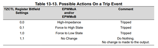
I found in the Technical Reference Module that software-forced tripping is supported in TMS320F280037, but did not find any example of how can I do it.
At this moment my code is very large, so I will put only some fragments of the main parts, could you help me inserting one example of the software-forced tripping for ePWM1 in it?
#include "driverlib.h"
#include "device.h"
int duty_cycle = 50;
__interrupt void isr_adc_A(void); // ADC interruption
int main(void)
{
InitSysCtrl(); // Initialize device clock and peripherals
DINT; // Disable CPU interrupts
InitPieCtrl(); // Initializes the PIE control registers to a known state
IER = 0x0000; // Disable CPU interrupts
IFR = 0x0000; // Clear all CPU interrupt flags
InitPieVectTable(); // Initialize the PIE vector table
// Setups
Setup_GPIO(); // Setup GPIO's
Setup_ePWM(); // Setup ePWM's
Setup_ADC(); // Setup ADC
// ISR interrupts
EALLOW;
PieVectTable.ADCA1_INT = &isr_adc_A; // Redirect function to ADC_A interruption
EDIS;
// Enable PIE interrupt
PieCtrlRegs.PIEIER1.bit.INTx1 = 1; // Enable column 1 for ADC1 at line 1
//PIE Channel Lines
IER |= M_INT1;
EINT; //Enable Global interrupt INTM
ERTM; //Enable Global realtime interrupt DBGM
while(1)
{
EPwm1Regs.CMPA.bit.CMPA = duty_cycle;
DELAY_US(5000000);
}
return 0;
}
__interrupt void isr_adc_A(void)
{
duty_cycle = duty_cycle+1;
AdcaRegs.ADCINTFLGCLR.bit.ADCINT1 = 1; // Clear INT1 flag
PieCtrlRegs.PIEACK.all = PIEACK_GROUP1; // Clear PIEIFR
}
void Setup_GPIO(void)
{
EALLOW;
//PWM 1
GpioCtrlRegs.GPAGMUX1.bit.GPIO0 = 0; //Select the GMUX for PWM 1A
GpioCtrlRegs.GPAMUX1.bit.GPIO0 = 1; //Select the MUX for PWM 1A
GpioCtrlRegs.GPAPUD.bit.GPIO0 = 1; //Disable pull-up resistor for PWM 1A
GpioCtrlRegs.GPAGMUX1.bit.GPIO1 = 0; //Select the GMUX for PWM 1B
GpioCtrlRegs.GPAMUX1.bit.GPIO1 = 1; //Select the MUX for PWM 1B
GpioCtrlRegs.GPAPUD.bit.GPIO1 = 1; //Disable pull-up resistor for PWM 1B
EDIS;
}
void Setup_ePWM(void)
{
EALLOW; //Allow edition
CpuSysRegs.PCLKCR2.bit.EPWM1 = 1; //Enable ePWM1
CpuSysRegs.PCLKCR2.bit.EPWM2 = 1; //Enable ePWM2
CpuSysRegs.PCLKCR2.bit.EPWM3 = 1; //Enable ePWM3
CpuSysRegs.PCLKCR2.bit.EPWM4 = 1; //Enable ePWM4
CpuSysRegs.PCLKCR2.bit.EPWM5 = 1; //Enable ePWM5
CpuSysRegs.PCLKCR2.bit.EPWM7 = 1; //Enable ePWM7
CpuSysRegs.PCLKCR2.bit.EPWM8 = 1; //Enable ePWM8
CpuSysRegs.PCLKCR0.bit.TBCLKSYNC = 0; //Start synchrony with others PWM
//PWM 1
EPwm1Regs.TBPRD = 1200; //Set timer period (120e6)/(1*2)
EPwm1Regs.TBPHS.bit.TBPHS = 0; //Set phase shift
EPwm1Regs.EPWMSYNCOUTEN.all = SYNC_OUT_SRC_ENABLE_ALL;
EPwm1Regs.TBCTR = 0x0000; //Clear counter
EPwm1Regs.TBCTL.bit.CTRMODE = TB_COUNT_UPDOWN; //Count up/down
EPwm1Regs.TBCTL.bit.PHSEN = TB_DISABLE; //Disable phase shift
EPwm1Regs.TBCTL.bit.HSPCLKDIV = TB_DIV1; //Prescale high speed clock
EPwm1Regs.TBCTL.bit.CLKDIV = TB_DIV1; //Prescale low speed clock
EPwm1Regs.CMPCTL.bit.SHDWAMODE = CC_SHADOW; //Avoid multiples switching
EPwm1Regs.CMPCTL.bit.LOADAMODE = CC_CTR_ZERO_PRD; //Refresh duty cycle on top and base of triangular wave
EPwm1Regs.CMPCTL.bit.SHDWBMODE = CC_SHADOW; //Same thing for module B
EPwm1Regs.CMPCTL.bit.LOADBMODE = CC_CTR_ZERO_PRD; //Same thing for module B
EPwm1Regs.DBCTL.bit.POLSEL = DB_ACTV_HIC; //Active Hi complementary
EPwm1Regs.DBCTL.bit.OUT_MODE = DB_FULL_ENABLE; //Enable Dead time module
EPwm1Regs.DBFED.bit.DBFED = 0; //Fall dead time (0.5 us)
EPwm1Regs.DBRED.bit.DBRED = 0; //Rise dead time (0.25 us)
EPwm1Regs.AQCTLA.bit.PRD = AQ_NO_ACTION; //Action when achieve PRD value (no action in this case)
EPwm1Regs.AQCTLA.bit.ZRO = AQ_NO_ACTION; //Action when achieve zero value (no action in this case)
EPwm1Regs.AQCTLA.bit.CAU = AQ_CLEAR; //Action when achieve counter up value (clear in this case)
EPwm1Regs.AQCTLA.bit.CAD = AQ_SET; //Action when achieve counter down value (set in this case)
EPwm1Regs.ETSEL.bit.SOCAEN = 1; //Enable Start of Conversion for module A
EPwm1Regs.ETSEL.bit.SOCASEL = ET_CTR_PRDZERO; //ADC trigger on top
EPwm1Regs.ETPS.bit.SOCAPRD = ET_1ST; //Trigger on the first even
// End Setup
CpuSysRegs.PCLKCR0.bit.TBCLKSYNC = 1; //Conclude synchrony with others PWM
EDIS; //End edition
}
void Setup_ADC(void)
{
//
// Setup VREF as internal
//
SetVREF(ADC_ADCA, ADC_INTERNAL, ADC_VREF3P3);
Uint16 acqps;
// Determine minimum acquisition window (in SYSCLKS) based on resolution
acqps = 26;
//ADC_A
EALLOW;
CpuSysRegs.PCLKCR13.bit.ADC_A = 1; // Turn on ADC A module
AdcaRegs.ADCCTL2.bit.PRESCALE = 6; // Set ADCCLK divider to /4
AdcaRegs.ADCCTL1.bit.INTPULSEPOS = 1; // Set pulse positions to late
AdcaRegs.ADCCTL1.bit.ADCPWDNZ = 1; // Power up the ADC
DELAY_US(1000); // 1ms delay to allow ADC time to power up
//ADC_IN_A0
AdcaRegs.ADCSOC0CTL.bit.CHSEL = 0; // Selection of the Pin A0
AdcaRegs.ADCSOC0CTL.bit.ACQPS = acqps; // Acquision window (27 SYSCLK cycles in this case)
AdcaRegs.ADCSOC0CTL.bit.TRIGSEL = 0x05; // ePWM1A will be responsible to trigger ADC
AdcaRegs.ADCINTSEL1N2.bit.INT1SEL = 0; // end of SOC0 will set INT1 flag
AdcaRegs.ADCINTSEL1N2.bit.INT1E = 1; // enable INT1 flag
AdcaRegs.ADCINTFLGCLR.bit.ADCINT1 = 1; // make sure INT1 flag is cleared
EDIS;
}