This thread has been locked.

If you have a related question, please click the "Ask a related question" button in the top right corner. The newly created question will be automatically linked to this question.

TMS320F28379D: CAN COMMUNICATION PROBLEM F28379D

Part Number: TMS320F28379D

Hi, 

I am working on CAN communication with the F28379D and the F28377S. I have run some code composer examples like the can_simple_transmit or the can_external_transmit. I have configured the F28379D with CAN_B and the other with CAN_A, with the oscilloscope I can see the data transmission of the CAN_B but I can not see in the CCS the data arrival. It is as if the receiver was not listening to me.
Perhaps you can help me with this information, I have read some forums and I have downloaded some codes but I have the same problem.

  • Marco,

                Did you go through the debug tips in www.ti.com/lit/SPRACE5? Most problems can be resolved by evaluating the tips I have provided. 

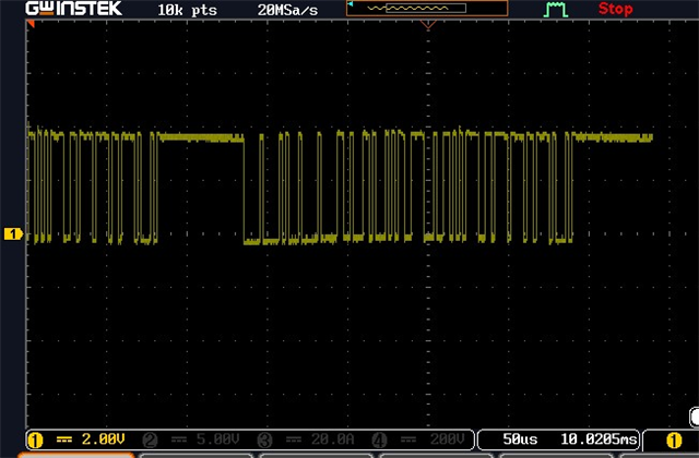
    Please share the oscilloscope capture from the transmit side. i.e. the CANTX pin. The waveform should be  clear enough that I am able to deduce the bit duration from it. Refer to SPRACE5 for sample waveforms. That is the level of clarity I am expecting. 

    Look at the value of the CANES register. It can provide you some clue on what might be going on. 

    Can you share the schematics of your boards with me privately? You can do this by initiating a friendship request with me first. You can do so by choosing the "Request Friendship" option when you hover the cursor over my name. Also please share the wiring diagram of your bus. Figure 1-1. Typical CAN bus in www.ti.com/lit/SPRACU9 shows you the correct method.

  • The code is the next.

    #include "driverlib.h"
    #include "device.h"


    #define TXCOUNT 100000
    #define MSG_DATA_LENGTH 8
    #define TX_MSG_OBJ_ID 1


    volatile unsigned long i;
    volatile uint32_t txMsgCount = 0;
    uint16_t txMsgData[8];


    void main(void)
    {

    Device_init();

    Device_initGPIO();
    GPIO_setPinConfig(DEVICE_GPIO_CFG_CANRXB);
    GPIO_setPinConfig(DEVICE_GPIO_CFG_CANTXB);

    CAN_initModule(CANB_BASE);

    CAN_setBitRate(CANB_BASE, DEVICE_SYSCLK_FREQ, 500000, 16);


    CAN_setupMessageObject(CANB_BASE, TX_MSG_OBJ_ID, 0x1,
    CAN_MSG_FRAME_STD, CAN_MSG_OBJ_TYPE_TX, 0,
    CAN_MSG_OBJ_NO_FLAGS, MSG_DATA_LENGTH);

    txMsgData[0] = 0x01;
    txMsgData[1] = 0x23;
    txMsgData[2] = 0x45;
    txMsgData[3] = 0x67;
    txMsgData[4] = 0x89;
    txMsgData[5] = 0xAB;
    txMsgData[6] = 0xCD;
    txMsgData[7] = 0xEF;


    CAN_startModule(CANB_BASE);

    while(1)

    {
    CAN_sendMessage(CANB_BASE, TX_MSG_OBJ_ID, MSG_DATA_LENGTH, txMsgData);

    while(((HWREGH(CANB_BASE + CAN_O_ES) & CAN_ES_TXOK)) != CAN_ES_TXOK)
    {
    }
    }

    asm(" ESTOP0");
    }

  • It does look like a valid CAN frame. However, please provide a zoomed-in waveform. I need to confirm the bit-width is 2us (since you are using 500 kbps). Also, please measure the signal at the CANRX pin of the receiver. If There is no arbitration on the bus (i.e. you only have two nodes on the bus, one being the transmitter and the other being a receiver), the waveform at the CANTX pin of the transmitter and the CANRX pin of the receiver will be exactly identical with the exception of the ACK bit in the CANRX pin of the receiver. Note that the ACK is generated by the receiver, not the transmitter. I have explained all this in SPRACE5.

    I have accepted your friendship request, so go ahead and send me the schematics and the wiring diagram for your circuit. 

  • Hareesh, 

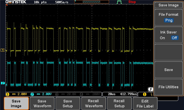
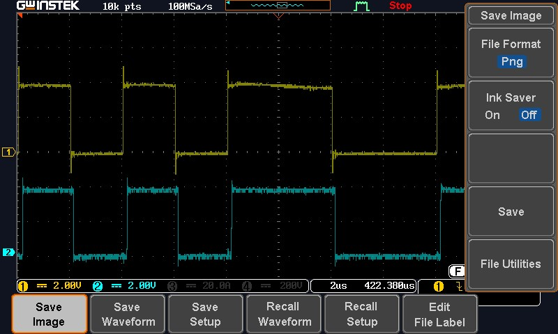
    I connect CAN-H y CAN_L between the F28379D and LAUNCHPAD F28377S. But the signals are similar, the receiver don't generated ACK. 

    The yellow line is measured on the CANTX pin of the transmitter and the blue line on the CANRX pin of the receiver. 

    The bit-width is 2us.

  • Did you connect the grounds (GND) of the boards together?

  • Yes, the both GND are connected. 

  • Scope the signals on the CANTX & CANRX pins of the transmitter. It should look identical to Figure 2-6. Waveform at the CANRXA Pin in SPRACE5A. if you are able to successfully monitor the ACK signal from the receiver, then the message transmission is successful. I am afraid I cannot help you beyond this.

  • Hareesh, I have CAN communication, but now I need to send float number.

    change the code  in both codes but 

    uint16_t txMsgData_1[8]={0x21,0x32,0x23,0x14,0x45,0x26,0x27,0x18};

    to 
    float txMsgData_1[8]={3.3, 4.2, 4.5, 5.4, 3.6, 7.8, 9.8,19.42 };

    and 

    float rxMsgData[8];

    but the data is different in the  reception. 


  • Marco,

        This is not a CAN issue. CAN only supports the transmission of bytes. It does not know (or care) exactly what it is transmitting. Whatever bytes you write on the transmitter side will be transmitted and faithfully received by the receiver.  To summarize, the CAN protocol does not natively support transmission of floating-point numbers. The conversion of F.P numbers into suitable bytes on the transmitter side (and the reverse operation on the receiver side) must be handled by your software. CAN has nothing to do with it.