Part Number: TMS320F280049C
Other Parts Discussed in Thread: TMDSHSECDOCK, , C2000WARE, SYSCONFIG, LAUNCHXL-F280049C
Hi,
I am trying to accomplish something similar to what is described here: Sync PWM with an External Signal - TI Hercules Microcontroller (please check the video of this link to understand the functionality).
The main idea behind the post is to synchronise a PWM with an external signal where, every time the controlling signal has a rising edge the PWM signal is reset. The implementation is done with another TI microcontroller, therefore I guess it can be implemented as well with F28004x C2000 microcontroller family. In my case, I am using the TMS320F280049C control card along with TMDSHSECDOCK.
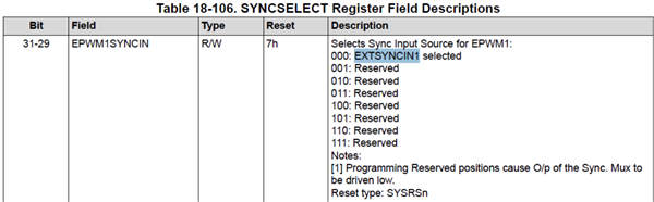
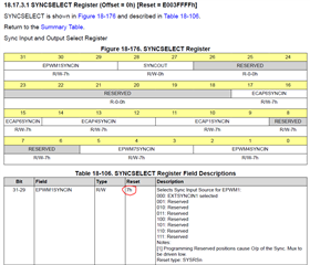
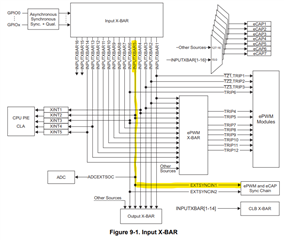
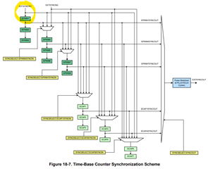
The TMS320F28004x Real-Time Microcontrollers Technical Reference Manual explains that an ePWM can be synchronised with EXTSYNCINx, hence the external sync signal should be directly routed through INPUTXBAR5 and/or INPUTXBAR6 in order to provide the synchronisation to ePWM and eCAP Sync Chain.
In order to test the concept I took the CCS reference example epwm_ex3_synchronization.projectspec (located at C2000Ware_5_00_00_00\driverlib\f28004x\examples\epwm) and did some modifications to make the test very simple. Thus, I considered the following simple scenario:
Input GPIO39* > INPUTXBAR5 > EXTSYNCIN1 > ePWM1 > GPIO0 (PWM1A) and GPIO1 (PWM1B) output
*External square signal (2V amplitude, 50% duty cycle and 100Hz) is applied to GPIO39
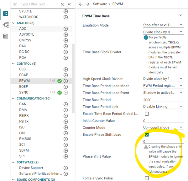
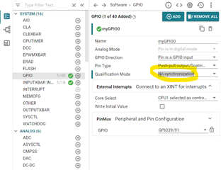
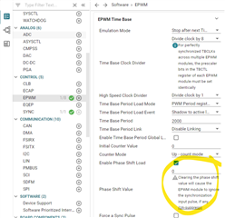
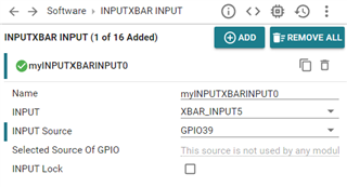
The final .c code is shared here below where my only contribution is to comment the lines related to ePWM2, 3 and 4 that I am not going to use. Also small modifications are applied on .syscfg code below, where I changed the XBAR input 5 to GPIO39 and deleted the myINPUTXBARINPUT1 (XBAR_INPUT6), the following screenshot shows the final config. Moreover, I deleted the myEPWM2, 3 and 4, the following screenshot shows the final config. No further changes are applied to the original example.
//#############################################################################
//
// FILE:   epwm_ex3_synchronization.c
//
// TITLE:  ePWM Using The Synch Chain and Phase Shift.
//
//! \addtogroup driver_example_list
//! <h1>ePWM Synchronization</h1>
//!
//! This example configures ePWM1, ePWM2, ePWM3 and ePWM4 as follows
//!  - ePWM1 without phase shift as sync source
//!  - ePWM2 with phase shift of 300 TBCLKs
//!  - ePWM3 with phase shift of 600 TBCLKs
//!  - ePWM4 with phase shift of 900 TBCLKs
//!
//! \b External \b Connections \n
//! - GPIO0 EPWM1A
//! - GPIO1 EPWM1B
//! - GPIO2 EPWM2A
//! - GPIO3 EPWM2B
//! - GPIO4 EPWM3A
//! - GPIO5 EPWM3B
//! - GPIO6 EPWM4A
//! - GPIO7 EPWM4B
//!
//! \b Watch \b Variables \n
//! - None.
//
//#############################################################################
//
//
// $Copyright:
// Copyright (C) 2023 Texas Instruments Incorporated - http://www.ti.com/
//
// Redistribution and use in source and binary forms, with or without
// modification, are permitted provided that the following conditions
// are met:
//
//   Redistributions of source code must retain the above copyright
//   notice, this list of conditions and the following disclaimer.
//
//   Redistributions in binary form must reproduce the above copyright
//   notice, this list of conditions and the following disclaimer in the
//   documentation and/or other materials provided with the
//   distribution.
//
//   Neither the name of Texas Instruments Incorporated nor the names of
//   its contributors may be used to endorse or promote products derived
//   from this software without specific prior written permission.
//
// THIS SOFTWARE IS PROVIDED BY THE COPYRIGHT HOLDERS AND CONTRIBUTORS
// "AS IS" AND ANY EXPRESS OR IMPLIED WARRANTIES, INCLUDING, BUT NOT
// LIMITED TO, THE IMPLIED WARRANTIES OF MERCHANTABILITY AND FITNESS FOR
// A PARTICULAR PURPOSE ARE DISCLAIMED. IN NO EVENT SHALL THE COPYRIGHT
// OWNER OR CONTRIBUTORS BE LIABLE FOR ANY DIRECT, INDIRECT, INCIDENTAL,
// SPECIAL, EXEMPLARY, OR CONSEQUENTIAL DAMAGES (INCLUDING, BUT NOT
// LIMITED TO, PROCUREMENT OF SUBSTITUTE GOODS OR SERVICES; LOSS OF USE,
// DATA, OR PROFITS; OR BUSINESS INTERRUPTION) HOWEVER CAUSED AND ON ANY
// THEORY OF LIABILITY, WHETHER IN CONTRACT, STRICT LIABILITY, OR TORT
// (INCLUDING NEGLIGENCE OR OTHERWISE) ARISING IN ANY WAY OUT OF THE USE
// OF THIS SOFTWARE, EVEN IF ADVISED OF THE POSSIBILITY OF SUCH DAMAGE.
// $
//#############################################################################

//
// Included Files
//
#include "driverlib.h"
#include "device.h"
#include "board.h"


__interrupt void epwm1ISR(void);
__interrupt void epwm2ISR(void);
__interrupt void epwm3ISR(void);
__interrupt void epwm4ISR(void);

//
// Main
//
void main(void)
{
    //
    // Initialize device clock and peripherals
    //
    Device_init();

    //
    // Disable pin locks and enable internal pull ups.
    //
    Device_initGPIO();

    //
    // Initialize PIE and clear PIE registers. Disables CPU interrupts.
    //
    Interrupt_initModule();

    //
    // Initialize the PIE vector table with pointers to the shell Interrupt
    // Service Routines (ISR).
    //
    Interrupt_initVectorTable();

    //
    // Assign the interrupt service routines to ePWM interrupts
    //
    Interrupt_register(INT_EPWM1, &epwm1ISR);
    //Interrupt_register(INT_EPWM2, &epwm2ISR);
    //Interrupt_register(INT_EPWM3, &epwm3ISR);
    //Interrupt_register(INT_EPWM4, &epwm4ISR);


    // Disable sync(Freeze clock to PWM as well). GTBCLKSYNC is applicable
    // only for multiple core devices. Uncomment the below statement if
    // applicable.
    //
    // SysCtl_disablePeripheral(SYSCTL_PERIPH_CLK_GTBCLKSYNC);
    SysCtl_disablePeripheral(SYSCTL_PERIPH_CLK_TBCLKSYNC);

    //

    // Configure GPIO0/1 , GPIO2/3 and GPIO4/5 and GPIO6/7 as
    // ePWM1A/1B, ePWM2A/2B, ePWM3A/3B, ePWM4A/4B pins respectively
    // Configure EPWM Modules
    //
    Board_init();

    //
    // Enable sync and clock to PWM
    //
    SysCtl_enablePeripheral(SYSCTL_PERIPH_CLK_TBCLKSYNC);

    //
    // Enable ePWM interrupts
    //
    Interrupt_enable(INT_EPWM1);
    //Interrupt_enable(INT_EPWM2);
    //Interrupt_enable(INT_EPWM3);
    //Interrupt_enable(INT_EPWM4);

    //
    // Enable Global Interrupt (INTM) and realtime interrupt (DBGM)
    //
    EINT;
    ERTM;

    //
    // IDLE loop. Just sit and loop forever (optional):
    //
    for(;;)
    {

    }
}

//
// epwm1ISR - ePWM 1 ISR
//
__interrupt void epwm1ISR(void)
{
    //
    // Clear INT flag for this timer
    //
    EPWM_clearEventTriggerInterruptFlag(myEPWM1_BASE);

    //
    // Acknowledge interrupt group
    //
    Interrupt_clearACKGroup(INTERRUPT_ACK_GROUP3);
}

//
// epwm2ISR - ePWM 2 ISR
//
/*__interrupt void epwm2ISR(void)
{
    //
    // Clear INT flag for this timer
    //
    EPWM_clearEventTriggerInterruptFlag(myEPWM2_BASE);

    //
    // Acknowledge interrupt group
    //
    Interrupt_clearACKGroup(INTERRUPT_ACK_GROUP3);
}

//
// epwm3ISR - ePWM 3 ISR
//
__interrupt void epwm3ISR(void)
{
    //
    // Clear INT flag for this timer
    //
    EPWM_clearEventTriggerInterruptFlag(myEPWM3_BASE);

    //
    // Acknowledge interrupt group
    //
    Interrupt_clearACKGroup(INTERRUPT_ACK_GROUP3);
}

//
// epwm4ISR - ePWM 4 ISR
//
__interrupt void epwm4ISR(void)
{
    //
    // Clear INT flag for this timer
    //
    EPWM_clearEventTriggerInterruptFlag(myEPWM4_BASE);

    //
    // Acknowledge interrupt group
    //
    Interrupt_clearACKGroup(INTERRUPT_ACK_GROUP3);
}*/
/**
 * These arguments were used when this file was generated. They will be automatically applied on subsequent loads
 * via the GUI or CLI. Run CLI with '--help' for additional information on how to override these arguments.
 * @cliArgs --device "F28004x" --package "F28004x_100PZ" --part "F28004x_100PZ" --context "system" --product "C2000WARE@5.00.00.00"
 * @versions {"tool":"1.18.0+3266"}
 */

/**
 * Import the modules used in this configuration.
 */
const epwm             = scripting.addModule("/driverlib/epwm.js", {}, false);
const epwm1            = epwm.addInstance();
const inputxbar        = scripting.addModule("/driverlib/inputxbar.js", {}, false);
const inputxbar1       = inputxbar.addInstance();
const inputxbar_input  = scripting.addModule("/driverlib/inputxbar_input.js");
const inputxbar_input1 = inputxbar_input.addInstance();
const sync             = scripting.addModule("/driverlib/sync.js");

/**
 * Write custom configuration values to the imported modules.
 */
epwm1.$name                                                    = "myEPWM1";
epwm1.epwmTimebase_period                                      = 2000;
epwm1.epwmCounterCompare_cmpA                                  = 1000;
epwm1.epwmCounterCompare_cmpB                                  = 500;
epwm1.epwmTimebase_counterMode                                 = "EPWM_COUNTER_MODE_UP";
epwm1.epwmTimebase_clockDiv                                    = "EPWM_CLOCK_DIVIDER_8";
epwm1.epwmTimebase_hsClockDiv                                  = "EPWM_HSCLOCK_DIVIDER_1";
epwm1.epwmActionQualifier_EPWM_AQ_OUTPUT_A_ON_TIMEBASE_ZERO    = "EPWM_AQ_OUTPUT_HIGH";
epwm1.epwmActionQualifier_EPWM_AQ_OUTPUT_B_ON_TIMEBASE_ZERO    = "EPWM_AQ_OUTPUT_HIGH";
epwm1.epwmActionQualifier_EPWM_AQ_OUTPUT_A_ON_TIMEBASE_UP_CMPA = "EPWM_AQ_OUTPUT_LOW";
epwm1.epwmActionQualifier_EPWM_AQ_OUTPUT_B_ON_TIMEBASE_UP_CMPB = "EPWM_AQ_OUTPUT_LOW";
epwm1.epwmEventTrigger_enableInterrupt                         = true;
epwm1.epwmEventTrigger_interruptEventCount                     = "1";
epwm1.epwmTimebase_syncOutPulseMode                            = "EPWM_SYNC_OUT_PULSE_ON_COUNTER_ZERO";
epwm1.epwm.$assign                                             = "EPWM1";
epwm1.epwm.epwm_aPin.$assign                                   = "GPIO0";
epwm1.epwm.epwm_bPin.$assign                                   = "GPIO1";

inputxbar1.$name = "myINPUTXBAR5";

inputxbar_input1.$name          = "myINPUTXBARINPUT0";
inputxbar_input1.inputxbarInput = "XBAR_INPUT5";
inputxbar_input1.inputxbarGpio  = "GPIO39";
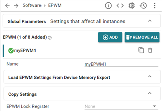
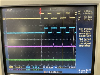
After loading the code I can not see any synchronisation at the rising edge of GPIO39 input. At the bottom of the post I attach a video in .ZIP format with the performed test, you can see the configuration and the result from the oscilloscope. In yellow is displayed the GPIO39 external control signal while in blue and pink the GPIO0 (PWM1A) and GPIO1 (PWM1B)
What may be missing on this example to make PWM synchronised? Why the PWM1A and PWM1B are not complementary?
Awaiting your answers.
Best regards,
Denys Ovsiyenko
VIDEO HERE - VideoTest.zip