This thread has been locked.

If you have a related question, please click the "Ask a related question" button in the top right corner. The newly created question will be automatically linked to this question.

DRV8353RS-EVM: DRV8353RS-EVM

Part Number: DRV8353RS-EVM
Other Parts Discussed in Thread: DRV8353,

Hello Team,

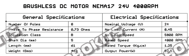
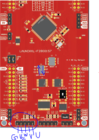
We are working on DRV8353 and TI launchpad F280015x for BLDC motor application. We have below query while interfacing with TI driver board and launch pad.

I configured with UCC code, I enabled the following macros HVMTRPFC_REV1P1, ENC, BSXL8353RS on the motor1_driver.c file.

Witch are the macros have to configure for DRV8353 and TI launchpad F280015x.

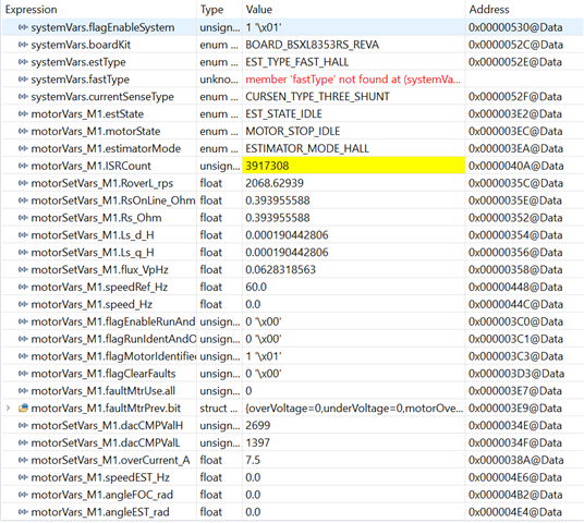
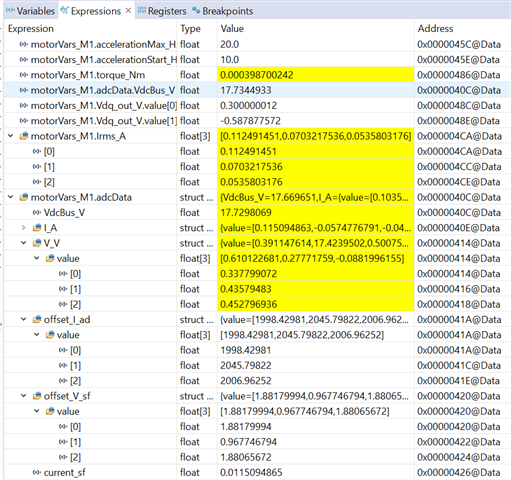
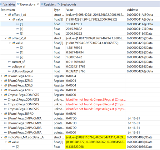
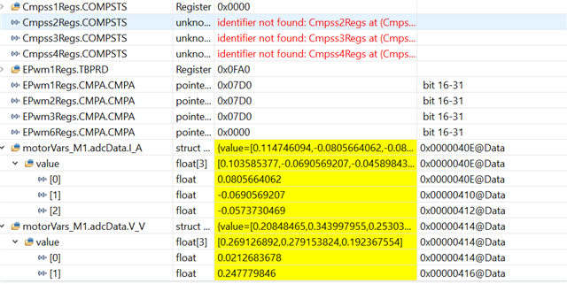
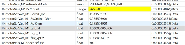
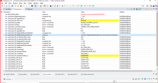
Input bus voltage : 24v I given. But it's not reading the input bus voltage. On the motorVars_M1.adcData.VdcBus_V variable 

Can you help understand what we are missing?

Any help is much appreciated. Thanks in Advance.

Thanks & Regards,

T.Premkumar.

  • Hello T. Premkumar,

    Apologies for the delay in response. The current iteration of the Universal Motor Control Lab for the F280015x (from C2000 Motor Control SDK version 5.00.00.00) does not yet have support for the DRV8353RS-EVM. The predefine macro HVMTRPFC_REV1P1 is for a specific hardware kit- the TMDSHVMTRINSPIN. You can adapt the project to support the DRV8353RS-EVM (using the implementation for the other devices, such as the F280013x as a reference). Without making those alterations, as described in the Universal Motor Control Lab User's Guide, the project is not likely to be fully functional.

    Regards,
    Jason Osborn

  • Dear Jason Osborn,

    Thank you your response.

    On Universal Motor Controller sdk code witch are the files I need to modify? 

    I taken the reference from F280025c example code. In the many file I need to change. Could you brief me more? 

    Or I requesting you to can we have a shot call. So, Help as to resolve this issue quickly.

    Thanks,

    Premkumar.T

  • Hello again Premkumar,

    I've sent you a friend request here on the e2e forum. Once you accept, I'll send you a draft excerpt from the next, unreleased version of the user's guide for the Universal Motor Control Lab. This excerpt covers 2 sections which, when used together, describe how to port the lab from one C2000 MCU to a different C2000 MCU.

    First, read section 5.3 'Porting Reference Code to New C2000 MCU'. The written instructions here will eventually point you to read section 5.1.2 'Migrating Reference Code to a Custom Board'.

    Regards,
    Jason Osborn

    Note: For any other readers, if you need this excerpt as well, please contact me using the private message here on the e2e forums and I will share the draft excerpt. Once the next iteration of the User's Guide has been published, I will edit this post.

  • Hello ,

    Thanks for the Document.

    We Tried configured code based on F280025C to F2800157 Launchpad interface with Drv8353. We are able to read analog pins perfectly but motor not running.

    During debug mode, GUI Expression window ISR increment and Bus voltage reading perfectly.

    Pin mapping done based on Launchpad F2800157 to Drv8353, GPIO26 used as EQEP2I and SPI_CS added JUMPER from GPIO11 to DRV CS PIN.

    We used PMSM motor with HALL Sensor.

    Pre-Defined Symbols used: 

    MOTOR1_HALL

    BSXL8353RS_REVA

    MOTOR1_FAST

    We need code review support from TI.

    Any help is much appreciated. Thanks in Advance.

  • I have replied to the private message I received. As efforts continue, I will update and/or resolve this thread if it becomes necessary.

    Regards,
    Jason Osborn

  • Hello  

    Thanks for the confirmation.

    Will check internally and come back to you.

    Thanks

  • Hello @Jason Osborn

    Thanks for your response.

    1)Have you adjusted the copied .cmd files &. project spec file?
    yes, because we used existing .cmd files for F2800157.
    2) any warning or error?
    No
    3)have you set 'motorVars_M1. flagEnableRunAndIdentify=1' once initialization is complete?
    yes
    4)Please check if the following variables are showing correct values.
    . motorVars_M1. adcData.I_A
    . motorVars_M1. adcData.V_V
    Not sure the read values are correct attached Screenshot.
    5)Does the following variables have any values at all after you have set flagEnableRunAndIdentify ? it should
    No, when I set Ref Sped as 60 its start with 1.723 and drop to zero.

    6)Does the following variables have any values at all after you have set flagEnableRunAndIdentify ? it should
    . motorVars_M1.faultMtrUSe.all ---> always zero

    Good point here is when enable LEVEL2 build motor running at 60HZ speed but speed in GUI Expression is always zero.

    Right now, Vdc bus voltage reading wrong values.

    when i set RPS to 9V its always showing 17.xx voltage
    when i set RPS to 30V its always showing 17.xx voltage

    I feel, the current and voltage offset are not correct.

  • Hello ,

    As per latest updated, Able to read correct voltage (Voltage varying in all range) and Motor running in open loop (Build_Level_2) Successfully.

    But still not able to run motor in closed loop (BUILD_LEVEL_3 & BUILD_LEVEL_4). Its jerks actually and stop.

    During motor run got over current fault failure and motor stops immediately. How to resolve this ?

  • Hello again,

    Apologies for not getting back to you regarding the prev. message, it's been a bit hectic on my end.

    My instinct, when open loop (build 2) is working and both builds 3 and 4 are not working is that the motor's hardware parameters may not be correctly set in the user_mtr1.h file. Has the motor-specific section been updated to refer to your specific motor?

    Regards,
    Jason Osborn

  • Hello @Jason Osborn,

    Thanks for your reply.

    Yes, Updated parameter in user_mtr.h doesn't know its correct or not (I don't have motor spec). but got it through when enable motor identification " userParams_M1.flag_bypassMotorId = false;" is this way is correct to approach this?

  • I would recommend trying to find as much existing information as you can regarding a motor you're using, particularly to verify the functionality of a ported lab. Other than that, yes, that is correct, with three significant caveats.

    1. For identification to occur correctly, the FAST estimator should be active throughout identification.
    2. The initial value for the #define USER_MOTOR1_x parameters should be reasonably close to the true value- this value is usually determined by taking the motor datasheet/spec information. If the value is completely incorrect, it can cause the estimation to result in inaccurate values.
      1. USER_MOTOR1_RATED_FLUX_VpHz in particular can result in wildly incorrect values.
    3. The motor identification process is only fully functional in Build 4

    Additionally, I recalled one additional change you may need to make for the F280015x from the F28002x- depending on your version of the Motor Control SDK. Ensure the following is present in user_common.h:

    #define USER_SYSTEM_FREQ_Hz (float32_t)(DEVICE_SYSCLK_FREQ)

    Regards,
    Jason Osborn

  • Hello ,

    Thanks for your immediate response.

    1)Currently selected Macros.

    MOTOR1_HALL,

    BSXL8353RS_REVA,

    MOTOR1_FAST

    2)I have very limited spec information 

    3)Which mean in Build_Level2 we can't achieve complete parameters through motor identification flag??

    4)#define USER_SYSTEM_FREQ_Hz (float32_t)(DEVICE_SYSCLK_FREQ) this part of code is there in F280015x .

  • Hello,

    1. motorVars_M1.estimatorMode = ESTIMATOR_MODE_FAST during the estimation process
    2. There is certainly some useful information there.
      1. To convert phase-to-phase into phase-to-neutral (which is what the Motor Control SDK both expect), apply the following equation:
        1. USER_MOTOR1_Rs_Ohm = 
      2. Ensure that the parameters which include "_EST_CURRENT_A" are adjusted to match the rated current of the motor
      3. I recall there being a way to determine the Vp/Hz flux from the available information, but I can't find it immediately- I'll get back to you as soon as I can.
    3. Correct.
    4. Good to know, thank you for confirmation.

    Regards,
    Jason Osborn

  • Hi ,

    Thanks for your feedback.

    As per Latest update, Motor running in LEVEL 1, LEVEL2, LEVEL3 Build.

    Still Failing in LEVEL4 Build its starts and jerks but stopped with motor fault (Module over current.)

    In Level 3 Build motor running but "motorVars_M1.speed_Hz" always zero. initially, its start with 1.7342 and after that its always zero but motor running able to see values almost close to set value in "motorVars_M1.speedEST_Hz.

  • Were you able to confirm that the current value of motorVars_M1.estimatorMode = ESTIMATOR_MODE_FAST when running in build level 3? (displays as 0 in CCS)

    If FAST estimator (speedEST_Hz) is correct but the value of speed_Hz is not correct, that sounds like the HALL sensor is not working. Disabling MOTOR1_HALL may give better results.

    Regards,

    Jason Osborn

  • Hello @jason Osborn,

    Thank you very much for your support.

    Now I am able to run motor in BUILD_LEVEL_3 & BUILD_LEVEL_4 Successfully with all speed using Fast_Estimator.

    After disable MOTOR1_HALL ,with Fast Estimator (Sensor less) able to run motor.

    But still doubt on Hall Sensor interface on Launchpad F2800157 with Drv8353 connection.

    Right now, Hall sensor (U, V, W) connected to J13 & S5 ->Q1 to BP & S5->Q2 to J13.

    Any other changes have to do for Hall Sensor Connection.

  • Hello again,

    Since this is a conversion from a different board, my instinct here is that somewhere, something isn't being assigned to the right pin or internal routing. I would verify all work done to convert to the F2800157 for the MOTOR1_HALL predefine. I can personally verify that I've utilized it many times on the F280025C.

    Regards,
    Jason Osborn