This thread has been locked.

If you have a related question, please click the "Ask a related question" button in the top right corner. The newly created question will be automatically linked to this question.

TMS320F28335: Support on SPI communication to the external slave device

Part Number: TMS320F28335

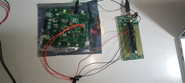
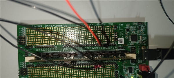
We are trying to make a SPI communication in F28335 device, and by sending the data from our TMS320F28335 SPI (MASTER) to external Slave device of HOLT INTEGRATED CIRCUIT HI-35850 (SLAVE) device board.

Here, We have configured the TMS320F28335 SPI device as a MASTER and HI-35850 as a SLAVE.

  • For this, we were trying to send the Arinc data which is a 32 bits by 4 iterations, since we have configured SPICCR.bit.SPICHAR for a 8-bit word. 
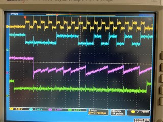
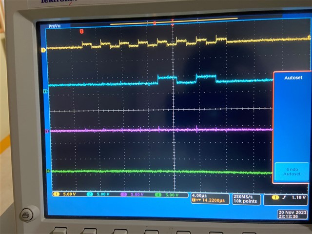
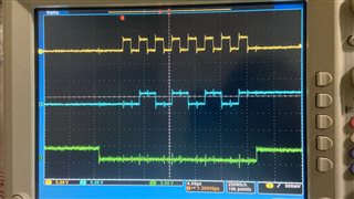
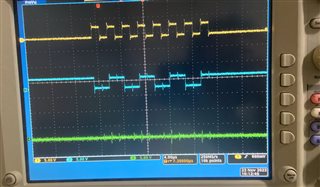
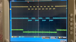
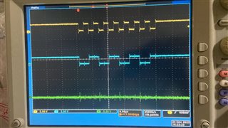
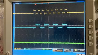
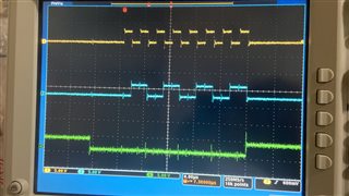
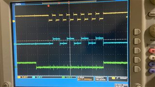
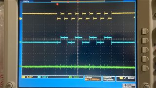
  • We have captured and attached as a attachments Waveforms in 4-channel CRO with the SCLK, MISO, MOSI and CS.  But we were unable to see more than 16-clocks in the waveforms and the Chip select (CS) was getting de-asserted, but we need 32 clocks for 32 bit and we need your support on this.
  • And I had attached my C code below for SPI for this, along with Initialization and configuration in the module name Mcu1_Spi_initialization().  

#include "Mcu1_Device.h"
#include "Mcu1_Timer.h"
#include "stdio.h"
#include "Mcu1_Arinc429.h"
#include "Mcu1_Spi.h"
#include "Mcu1_Arinc429_SPI.h"

void main(void)
{
    // Initialize System Control:PLL, WatchDog
    InitSysCtrl();

    // Disable CPU interrupts
    DINT;
    Gpio_init();
    InitPieCtrl();

    /* Disable all interrupts and clear all interrupt flags:*/
     IER = 0x0000;
     IFR = 0x0000;
     InitPieVectTable();

     /* Initialize GPIO pins */
    InitSpiaGpio();

    /*Call spi initialization*/
        Mcu1_Spi_initialization();

       /* j is for index increment */
        UNS8 j = 0;

        /* Tx data Variable */
        UNS8 Tdata = 0;

               SpiaRegs.SPITXBUF = 0x1000;
               SpiaRegs.SPITXBUF = 0x2000;
               SpiaRegs.SPITXBUF = 0x2000;
               for(j=0;j<=19;j++)
               {
               SpiaRegs.SPITXBUF = 0x0E00;
               SpiaRegs.SPITXBUF = 0x5500;
               SpiaRegs.SPITXBUF = 0x5500;
               SpiaRegs.SPITXBUF = 0x5500;
               SpiaRegs.SPITXBUF = 0x5500;
               Tdata = SpiaRegs.SPITXBUF;
               printf("transmitted data: 0x%X\n", Tdata);
               }
}

void InitSpiaGpio()
{

   EALLOW;

/* Enable pull-up for GPIO16, GPIO17, GPIO18 & GPIO19 */
    GpioCtrlRegs.GPAPUD.bit.GPIO16 = 0;   // (SPISIMOA)
    GpioCtrlRegs.GPAPUD.bit.GPIO17 = 0;   // (SPISOMIA)
    GpioCtrlRegs.GPAPUD.bit.GPIO18 = 0;   // (SPICLKA)
    GpioCtrlRegs.GPAPUD.bit.GPIO19 = 0;   // (SPISTEA)

    /* Asynchronous input for GPIO16, GPIO17, GPIO18 & GPIO19 */
    GpioCtrlRegs.GPAQSEL2.bit.GPIO16 = 3; // (SPISIMOA)
    GpioCtrlRegs.GPAQSEL2.bit.GPIO17 = 3; // (SPISOMIA)
    GpioCtrlRegs.GPAQSEL2.bit.GPIO18 = 3; // (SPICLKA)
    GpioCtrlRegs.GPAQSEL2.bit.GPIO19 = 3; //  (SPISTEA)

    /* Configure MUX register pins GPIO16, GPIO17, GPIO18 & GPIO19 */
    GpioCtrlRegs.GPAMUX2.bit.GPIO16 = 1; // SPISIMOA
    GpioCtrlRegs.GPAMUX2.bit.GPIO17 = 1; // SPISOMIA
    GpioCtrlRegs.GPAMUX2.bit.GPIO18 = 1; // SPICLKA
    GpioCtrlRegs.GPAMUX2.bit.GPIO19 = 1; // SPISTEA

    EDIS;
}

void Mcu1_Spi_initialization()
{

    EALLOW;
    /*Enabling peripheral clock*/
    SysCtrlRegs.PCLKCR0.bit.SPIAENCLK = 1;
    EDIS;

    /* Configuration for SPI */
    /**************************************************************************/
    /* SPI SW RESET to 0 */
    SpiaRegs.SPICCR.bit.SPISWRESET = 0;

    /*SPI network mode, making as master */
    SpiaRegs.SPICTL.bit.MASTER_SLAVE = 1;

    /*Enabling talk bit for transmit enable */
    SpiaRegs.SPICTL.bit.TALK = 1;

    /* Clock Polarity to 0 */
    SpiaRegs.SPICCR.bit.CLKPOLARITY = 0;

    /* Clock Phase to 0 */
    SpiaRegs.SPICTL.bit.CLK_PHASE = 0;

    /* SPI baud rate control*/
    SpiaRegs.SPIBRR = 0x27;      // SPI_BRR

    /* SPI Character bits to 8-bit word */
    SpiaRegs.SPICCR.bit.SPICHAR = 0x7;

    /* Clear OVERRUN Flag by giving 1 to this bit */
    SpiaRegs.SPISTS.bit.OVERRUN_FLAG = 1;

    /* Set SPIRSWRESET to 1  to release the SPI from reset state */
    SpiaRegs.SPICCR.bit.SPISWRESET = 1;

    /**************************************************************************/
}


Please visit to my attachments of the Waveforms and SPI code.  And kindly suggest me, what need to be corrected.

  • Hi Chaya,

    Please double check that the clock phase and polarity between F28335 and HI-35850 align. Could you try changing the polarity bit to 1? If this doesn't help, just want to make sure I have all context- is there any other code involved in the sending/receiving of data for F28335? You are operating in non-FIFO, F28335 master mode, with no interrupts, correct?

    Best Regards,

    Allison

  • Hi,

    1. Yes, we are operating in non-FIFO mode.
    2. TI F28335 as a MASTER mode.
    3. And no interrupts.

    Test Environment :

    • Host system (TI F28335 as the main controller) powered separately
    • ADK-35850  with HI-35850 powered together as a single assembly.


    Host SPI configuration (TI F28335):

    • Clearing SPI SWRESET to 0 for reset state, SpiaRegs.SPICCR.bit.SPISWRESET = 0;
    • Host as MASTER, SpiaRegs.SPICTL.bit.MASTER_SLAVE = 1;
    • Baud rate: 500 Khz, SpiaRegs.SPIBRR = 0x7F;
    • Transmitter enable, SpiaRegs.SPICTL.TALK = 1;
    • Configuring Host to Mode -‘0’, SpiaRegs.SPICCR.bit.CLKPOLARITY = 0; , & SpiaRegs.SPICTL.bit.CLK_PHASE = 0;
    • Host SPI 8-bit character, SpiaRegs.SPICCR.bit.SPICHAR = 0x7;
    • Clearing OVERRUN FLAG, SpiaRegs.SPISTS.bit.OVERRUN_FLAG = 1;
    • After these configuration, set SPI SWRESET to 1, SpiaRegs.SPICCR.bit.SPISWRESET = 1;


    Host SPI Bus pin Configuration (TI F28335):

    • Firstly we are enabling pull-up resistors for GPIO16 (MOSI), GPIO17 (MISO), GPIO18 (SCLK) & GPIO19 (SPISTE).
    • Set Asynchronous input for  GPIO16 (MOSI), GPIO17 (MISO), GPIO18 (SCLK) & GPIO19 (SPISTE).
    • Configured GPIO16 for MOSI, GpioCtrlRegs.GPAMUX2.bit.GPIO16 = 1;
    • Configured GPIO17 for MISO, GpioCtrlRegs.GPAMUX2.bit.GPIO17 = 1;
    • Configured GPIO18 for SCLK, GpioCtrlRegs.GPAMUX2.bit.GPIO18 = 1;


    • In order to keep SPISTE (CS) active throughout, configured GPIO19 for General Purpose I/O (GPIO), GpioCtrlRegs.GPAMUX2.bit.GPIO19 = 0;
      • GpioDataRegs.GPADAT.bit.GPIO19 = 0;
      • GpioCtrlRegs.GPADIR.bit.GPIO19 = 1; (for output)


    Interconnection between Host SPI (TI F28335) and HOLT HI-35850:

                    Test configuration details are below, please refer the Fig -2, Fig -3 and Fig -4 attached.

    • Host SPI MOSI (GPIO16) <-> HI-35850’s Serial Input (SI)
    • Host SPI MISO (GPIO17) <-> HI-35850’s Serial Output (SO)
    • Host SPI SCLK (GPIO18) <-> HI-35850’s Serial Clock (SCLK)
    • Host SPI SPISTE (GPIO19) <-> HI-35850’s Chip Select (CS)


    Test Conducted:

    • Configuring Host to Mode -‘0’, SpiaRegs.SPICCR.bit.CLKPOLARITY = 0; , & SpiaRegs.SPICTL.bit.CLK_PHASE = 0;
    • Transmitted "0x0A" data on SO and in response awaited for data "0x01" from the HOLT board
    • Observed that the no. of clock pulses were restricted to only 8, even though CS continued to remain in active state (refer the Fig -1 attached) and no data received from the HOLT HI-35850.


    Queries:

                    Clarifications needed from you for below queries,

    1. Please confirm either our configuration is correct for SPI to operate in Mode "0"?
    2. Please clarify why the no. of clock pulses are getting restricted to 8 clock cycles, in spite of keeping the CS/ active? 
    3. Please confirm whether the connection between Host SPI (TI F28335) and HOLT HI-35850 are correct?


    Requesting you to provide us your support on how to increase more than 8 clock pulses and get data received from the HOLT HI-35850.

     Thanks & Regards,

    Chaya 

  • Hi Chaya,

    Thank you so much for the organized information here, it is very helpful. Your SPI F28335 and GPIO configurations look correct to me so far. This is the correct setup for operating in Mode 0, but can I ask if you did try setting the polarity bit to '1'? In other words, can you please try to test with the only change being setting polarity for F28335 to '1' so that F28335 is operating in 'Mode 1' instead of 'Mode 0'? I've seen a similar issue to this between another device and HI-35850 and want to make sure we check if this resolves the issue first since it's a quick change to implement.

    Please let me know if this is able to resolve the issue or if you see different behavior.

    Best Regards,

    Allison

  • HI .

    Thanks for your immediate response.

    As, per your suggestion we tried for Mode 0 and remaining modes also, combinations as given in the table below:

    MODES

    CLOCK POLARITY

    CLOCK PHASE

    GPIO-19

    Figure

    0

    0

    0

    General Purpose I/O

    Fig 1

    0

    0

    0

    CS

    Fig 2

    1

    1

    0

    General Purpose I/O

    Fig 4

    1

    1

    0

    CS

    Fig 3

    2

    0

    1

    General Purpose I/O

    Fig 5

    2

    0

    1

    CS

    Fig 6

    3

    1

    1

    General Purpose I/O

    Fig 8

    3

    1

    1

    CS

    Fig 7


    In all the trials of combinations, we can see only 8-clock cycles in Waveforms while we were transmitting 8 different data’s and we have configured for 8-bit word.

    So, Please support us in how we can see more than 8 clock cycles.  For example, here I am transmitting 8-different data’s and we want to see (8-bit X 8) totally 64 clock cycles consecutively and Chip select (CS) should keep to low.


    Thanks & Regards,

    Chaya

  • Hi Chaya,

    Thank you for the scope shots of the testing. I also wanted to ask if you could clarify that the yellow is SPICLK, Green is SPISTE nd what is the blue signal (and what was the purple in the prior scope shots?) to be sure. Are you scoping both data lines to ensure that the correct data is being sent from both the F28335 and HI-35850 on each line during the time?  

    Also, I see that you are writing to the TXBUF for several lines of code in a row without a break, could you try adding in some delay between writes? Or have you considered using FIFO mode?

    Also, are you manually setting the SPISTE pin low at the beginning of data transmission and then setting back high at the end? This would ensure you are capturing the time that data is being sent.

    Best Regards,

    Allison

  • Hi,

             Thank you for your response.

             We have tried configuring the SPI for TMS320F28335, now we are getting 16 clock cycles and Chip select is also low as excepted..

            One more query we have on this, Now I am integrating TMS320F28335 and HI35850 and trying to communicate between Host SPI (TMS320F28335) and HI35850, I have configured TMS320F28335 for Mode 1 and as Master, but I am not able to see the communication between them. Please help us with this.

    We have a few query about this, Can we have a call regarding this issue.

    If yes please tell me your availability time to connect through Teams

  • Hi Chaya, 

    Glad you resolved the issue - I'd like to clarify a few things before trying to set up a call: 

    • What exact change did you implement to resolve the issue? Was it changing the clock mode to 1? Or add code to pull STE low and then high?
      • And instead of 8 clock pulses, you now see 16 in a row with no delay?
    • Are you able to provide scope shots of the 4 SPI lines during attempted communication? (SPICLK, both data lines, and SPISTE)
      • This is very helpful in debugging SPI communication issues as it can be quite apparent if one device or the other is not transmitting or receiving properly.
      • I also ask this because if this seems to be a HI35850 related inquiry, we should try to reach out to experts with that device as I my knowledge is on F28335. 
    • I think I may have misunderstood the original issue, as I had thought that you were able to communicate between the 2 devices, but unable to communicate the full data- could you clarify what the other oscilloscope channels were in the prior images you sent?

    Best Regards,

    Allison

  • Hi.

                    We are using TI 28335 processor board for one of our application and the SPI bus of this controller is used as host device to connect to HI-35850 ARINC-429 card . Our code was able to transmit A429 data through HI-35850 card and were trying to receive the data by externally looping back the transmitter to its receiver by using jumper wires

    Following are the tests carried out and observations made:

    • Looped the HI-35850 transmitter to its own receiver using external jumper wires
    • Transmitted ARINC 429 data 0x55AAFFC0
    • Read the status of HI-35850 Status register and observed that the RX FIFO is NOT empty thus ensuring data reception
    • Tried to read the RX FIFO by sending the opcode 0x08h followed by sending dummy no-op codes 0x00h, 0x00h, 0x00h, 0x00h in order to read the 32 bit data as per the sequence prescribed by HI-35850 user manual
    • While reading the data in this manner, we observed that the RXBUFF had data 0x55 after transmission of first 0x00h, and RXBUFF=0xAAh after transmission of second 0x00h, RXBUFF =0xFFh after transmission of third 0x00 and RXBUF = 0xC0h after transmission of last 0x00h
    • We tried to move the RXBUFF value in to a 8 bit array for converting them into a 32 bit word (RXDAT[I]= RXBUFF, i= 1 t0 4)
    • During this we observed that all the 4 array elements are filled with 0x00h
    • In order for improvement, we introduced a small delay between sending 0x00h and observed that RXDAT[1] alone was having 0x55h and the remaining 3 locations are all 0x00h
    • We declared the data type for RXDAT elements as a 32 bit word and observed that, except for the first data reading 0x00550000 and for remaining last three reading 0x00000000.


    We are just one step away in data transmission and reception using HI-35850 card and if this issue is resolved we are 100% done in understanding how to use this card for ARINC 429 transmission and reception.


    Request your understanding and immediate support to resolve the data read issue.

    Thanks & Regards,

    Chaya

  • Hi Chaya, 

    I am not familiar with the HI-35850 user manual, but I'd like to clarify the issue you are seeing:

    If I am understanding correctly, you are able to send and receive the 5 transmissions correctly for the four no-op codes sent (can you confirm that this data is the correct data communicated and you are not having an issue with the receival of this data via SPI any more?)

    So the main issue seems to be that there is something going wrong upon reading the received data? Since you are using 8-bit transmission, are you bit-shifting the data at all after receiving? Would you be able to share some of your program that is converting to a 32 bit word so I can take a look?

    Best Regards,

    Allison

  • Hi 

    Thank you for response,

    now we are facing another problem,

    Today we have tried for data reception from external Host SPI device.  The tests observations are carried out below:


    • I  tried to read the data (0x55AACCBBh) sent from external SPI device via TI F28335’s SPI . The 32 bit is read as 4 bytes using a for loop and tried to store in unsigned int32 variable
    • Here the very first time when I debug and run my code, we were able to see the entire 32 bit  data’s in SPI RXBUFF registers of TI F28335 device. But while storing that data into a temporary (unsigned int8) variable, and converting them into 32bit variable I was getting data stored as 0x00000000h
    • When I executed the .exe for the second time,  I see  only 3 bytes 0x55AACCh in the 32bit variable
    • I have attached my code below,
    • Request you to go through the code and suggest us the possible corrections to receive the data correctly


    /******************************************************************************/

    #include "Mcu1_Device.h"

    #include "Mcu1_Timer.h"

    #include "stdio.h"

    #include "Mcu1_Spi.h"


    void main(void)

      {

        UNS8 i_g;

        /*Initialize System Control:PLL, WatchDog*/

         InitSysCtrl();


        /* Disable CPU interrupts*/

        DINT;

        /* Initialize GPIO */

    //    Gpio_init();

    /******************************************************************************/

    /* Initialize the PIE control registers to their default state.*/

    /* The default state is all PIE interrupts disabled and flags

       are cleared.*/

    /******************************************************************************/

        InitPieCtrl();

        /* Disable all interrupts and clear all interrupt flags:*/

         IER = 0x0000;

         IFR = 0x0000;


    /******************************************************************************/

    /* Initialize the PIE vector table with pointers to the shell Interrupt

        Service Routines (ISR).*/

    /* This will populate the entire table, even if the interrupt

        is not used in this.  This is useful for debug purposes.*/

    /******************************************************************************/


        InitPieVectTable();

        InitSpiaGpio();

        Mcu1_Spi_initialization();


    /************************************************/

    /* Configuring the External SPI system */

        SpiaRegs.SPITXBUF = 0x01;

        SpiaRegs.SPITXBUF = Transmitting_Data_g[2];

        SpiaRegs.SPITXBUF = Transmitting_Data_g[3];

        SpiaRegs.SPITXBUF = Transmitting_Data_g[4];

    /***********************************************/

        for(i_g=0;i_g<=1000;i_g++)   

        {


        }

              Mcu1_Spi_tx();

    }

    void Mcu1_Spi_initialization()

    {


        EALLOW;

        /*Enabling peripheral clock*/

        SysCtrlRegs.PCLKCR0.bit.SPIAENCLK = 1;

        EDIS;


        /*Enabling character length control bit,Enabling SPI reset*/

        SpiaRegs.SPICCR.all = 0x0007;

        /*Enabling SPI interrupt*/

        SpiaRegs.SPICTL.bit.SPIINTENA = 1;

        /*Normal SPI clocking scheme*/

        SpiaRegs.SPICTL.bit.CLK_PHASE = 1;

        /*Enabling talk bit for transmit enable */

        SpiaRegs.SPICTL.bit.TALK = 1;

        /*SPI network mode, making as master */

        SpiaRegs.SPICTL.bit.MASTER_SLAVE = 1;

        /* SPI baud rate control*/

        SpiaRegs.SPIBRR = SPI_BRR;

        /* Transmit FIFO interrupt level bits setting to 2 words*/

        SpiaRegs.SPIFFTX.bit.TXFFIL = 2;

        /* Enabling TX FIFO Interrupt*/

        SpiaRegs.SPIFFTX.bit.TXFFIENA = 1;

        /*TX FIFO reset*/

        SpiaRegs.SPIFFTX.bit.TXFIFO = 1;

        /*SPI FIFO enable*/

        SpiaRegs.SPIFFTX.bit.SPIFFENA = 1;

        /*TX FIFO interrupt clear*/

        SpiaRegs.SPIFFTX.bit.TXFFINTCLR = 1;

        /*RX FIFO interrupt enable*/

        SpiaRegs.SPIFFRX.bit.RXFFIENA = 1;

        /*Receive FIFO interrupt level,making as 2 words*/

        SpiaRegs.SPIFFRX.bit.RXFFIL = 2;      // 2

        /*Receive FIFO interrupt clear */

        SpiaRegs.SPIFFRX.bit.RXFFINTCLR = 1;

        /*Receive FIFO reset */

        SpiaRegs.SPIFFRX.bit.RXFIFORESET = 1;

        SpiaRegs.SPICCR.bit.SPISWRESET = 1;


        EALLOW;

        /*Assign ISR to the SCI TX interrupt*/

        PieVectTable.SPITXINTA = &spi_tx_ISR;

        /*Assign ISR to the SCI RX interrupt*/

        PieVectTable.SPIRXINTA = &spi_rx_ISR;

        /*Peripheral initialization,enable the PIE block*/

        PieCtrlRegs.PIECTRL.bit.ENPIE = 1;

        /*here Enabling SCI RX interrupt in PIE group 9*/

        PieCtrlRegs.PIEIER6.bit.INTx2 = 1;

        /*here Enabling SCI TX interrupt in PIE group 9*/

        PieCtrlRegs.PIEIER6.bit.INTx1 = 1;

        EDIS;


        /*Enabling  interrupt*/

        EINT;

        /*Enabling Global real time interrupt DBGM*/

        ERTM;

        /*printing statement as transmission will start*/

        printf("transmitting\n");

    }

    void Mcu1_Spi_tx(void)

    {

        UNS32 RXd_Data = 0;

        UNS8 Temp = 0;

        UNS16 i=0;

        /*Checking if transmitter is ready for data*/

        if (SpiaRegs.SPIFFTX.bit.TXFFST == 0)

        {


            for(j_g=0;j_g<=10000;j_g++)        // intentionally delay given to receive the data; without this delay receiving only 0x00h

            {


            }


    /* Data reception */

            SpiaRegs.SPITXBUF = 0x0800;       // Transmit opcode for reading 32bit data

            for(i=0;i<=3;i++)                 // Loop for reading 4 bytes

            {

                RXd_Data = RXd_Data<<8;

                SpiaRegs.SPITXBUF = 0x0000;   // Transmit dummy data no opcode in order to receive the byte data

                Temp = SpiaRegs.SPIRXBUF;     // Read 4 bytes from 0 to 3 loops

                RXd_Data = RXd_Data|Temp;     // storing each byte into 32bit variable


            }

            printf("Received RXd data :0x%X%X\n", RXd_Data);

         }


        else

        {

            /*printing transmitter status*/

            printf("transmitter is not ready\n");

        }

    }

    Thanks & Regards,

    Chaya

  • Hi Chaya,

    One thing you can do is enable the "FREE" and "SOFT" bits of the SPIPRI register - when running CCS, actions such as polling memory, watch windows, breakpoints, etc. momentarily halts the CPU. It is possible this CCS activity can affect the operation of your application.

    Can you confirm that the 8-bit 'Temp' variable is holding the correct byte of data in each iteration of your 'for' loop? Or perhaps first save your data into an array form such as Temp[i] = SpiaRegs.SPIRXBUF; and you can bit-shift in the bytes to your RXd_Data after you check your full array is correct when debugging.

    Another suggestion would be to try removing the print statements, but since they aren't in ISRs I don't imagine that would affect anything in your case.

    Best Regards,

    Allison

  • Hi,


                    We tried whatever the suggestions you that have suggested us by enabling FREE and SOFT bits, even we are facing the same issue. 

    • When I was trying to run our code for first time after debugging, we were unable to store data in a variable.  But whenever am trying to re-run our code without debugging for the second time and only just re-run our code, we are able to store data.
    • We also another processor board (TI F28069) which is having same SPI interface.  In both the processors, we were able to see the data in RXBUFF in registers view.  However, when we are trying to copy the data into another variable for our data processing, we are getting the data as 0x00h.

                    This issue we were facing from more than a 1 week, considering our project pressure we need to resolve this issue at the earliest. We can arrange a call as per your availability time and hence need your immediate support to resolve this issue.  Please tell us your availability time to have call also.

    Thanks and Regards,

    Chaya

  • Hi Chaya,

    After you transmit a byte of data to the peripheral, the controller is reading too quickly from the SPIRXBUF. This is why you are seeing zeros upon first run (because no data has actually been received yet) and there is some leftover data read on the second run. My recommendations to resolve the issue are the following:

    • Send the op code and the four dummy no-op code bytes all in a row (without reading in between) so that the chip select pin stays low continuously throughout all transmission.
    • After sending the 5 bytes of data: You should then have a line in your program that checks the RX FIFO level status.
      • If the receive FIFO has at least 5 words (from the 5 transmissions), then you can start reading from the FIFO.
    • You can read the first word of the FIFO into some other temporary 16-bit variable to discard it.
    • After reading the first RXFIFO word to discard the byte received after transmitting the op-code, then you can read the 4 data bytes of the FIFO using a similar method to how you are doing it now.
      • My recommendation here is to keep 'Temp' as 16-bit, no need to use 8-bit (the 8-bits of actual data you want to receive will be kept in the lowest of the 16 bits, so OR-ing them in the next step will function same as you have now)
        • As a side note, if you wanted to you could optionally do a bitwise AND between the RXBUF and 0x00FF to make sure there are zeros in the upper 8 bits and only data in the lower 8 bits, but this is not required.
      • You can continue to do the bit-wise OR of RXd_Data|Temp for each byte to create the 32-bit RXd_Data

    In general, your program should always be checking that there is complete/valid data in the RXBUF before actually reading it. If you have a read command directly after a transmission command without checking for valid data, the controller reads faster than the SPI actually finishes transmitting, so issues occur with data reads.

    This should resolve it!

    Best Regards,

    Allison

  • Hi,

                    Thanks for your immediate response.  

    I prefer to have a call with you to present the problem in better manner, considering our project pressure we need to resolve this issue at the earliest.


    Following all the Tests we carried out today and observations made:

    • We tried as per your suggestions given yesterday.  By sending dummy no opcodes continuously without reading data in between.  The situation has worse than instead of improving as we could only read the first byte, even we execute many a times.
    • Since we had a doubt the timing margin for reading data we decreased and incremented the SPI clock frequency (290Khz to 2Mhz instead of earlier the 400Khz).  The observations were the same as yesterday, where we were able to read the 16bit data.


    Please let me know your availability for a call.


    Thanks & Regards,

    Chaya

  • We tried as per your suggestions given yesterday.  By sending dummy no opcodes continuously without reading data in between.  The situation has worse than instead of improving as we could only read the first byte, even we execute many a times.

    This is not what was suggested. Suggestion was:

            SpiaRegs.SPITXBUF = 0x0800;       // Transmit opcode for reading 32bit data
            SpiaRegs.SPITXBUF = 0x0000;   // Transmit dummy data no opcode in order to receive the byte data
            SpiaRegs.SPITXBUF = 0x0000;   // Transmit dummy data no opcode in order to receive the byte data
            SpiaRegs.SPITXBUF = 0x0000;   // Transmit dummy data no opcode in order to receive the byte data
            SpiaRegs.SPITXBUF = 0x0000;   // Transmit dummy data no opcode in order to receive the byte data
            
            >> You add code here to wait until SpiaRegs.SPIFFRX.RXFFST >= 5
            
            Temp = SpiaRegs.SPIRXBUF; // discard first byte (correspons to data received when opcode was sent)
            
            for(i=0;i<=3;i++)                 // Loop for reading 4 bytes
            {
                RXd_Data = RXd_Data<<8;
                Temp = SpiaRegs.SPIRXBUF;     // Read 4 bytes from 0 to 3 loops
                RXd_Data = RXd_Data|Temp;     // storing each byte into 32bit variable
            }

  • Hi,

                    In spite of our trails we are unable to store the received data into the variables declared.  Hence we strongly feel a call with you is preferable, let me know your availability for a call.


                    Tests carried out for this loop back test for HI-35850 from our TI F28335 Experiment kit, the data we are transmitting as [0xE0h, 0x11h, 0x11h, 0xC0h] as a Arinc word.  While we are receiving the data (whatever we transmitted for loop back) we are able to see same data in Oscilloscope on the SI(MISO) line of TI F28335 refer Attachment_1.pdf.  And the same data is also coming to RXBUF and RXEMU register, but when we are trying to transfer to a variable we were getting inconsistent data.  We are facing this issue from last 10days, hence we request to have a call with you for clarify this issue.  Also please find the our source code below request you go through suggest where ever corrections are required.


    Source Code:-


    #include "Mcu1_Device.h"

    #include "Mcu1_Timer.h"

    #include "stdio.h"

    #include "Mcu1_Spi.h"


    UNS16 Transmitting_Data_g[20] = {0x0A, 0x00, 0x10, 0x20, 0x20, 0x0B, 0x00, 0x00, 0x0E, 0xE0, 0x11, 0x11, 0xC0, 0x61, 0x11, 0xD0, 0xC0};

    UNS16 ReceivedData_g[10] = {0};

    UNS16 Transmitted_Data_g = 0, Dataregister_g = 0;

    UNS16 j_g = 0;


    void main(void)

      {

        UNS8 i_g;

        /*Initialize System Control:PLL, WatchDog*/

        InitSysCtrl();


        /* Disable CPU interrupts*/

        DINT;

    /******************************************************************************/

    /* Initialize the PIE control registers to their default state.*/

    /* The default state is all PIE interrupts disabled and flags

       are cleared.*/

    /******************************************************************************/

        InitPieCtrl();

        /* Disable all interrupts and clear all interrupt flags:*/

         IER = 0x0000;

         IFR = 0x0000;


    /******************************************************************************/

    /* Initialize the PIE vector table with pointers to the shell Interrupt

        Service Routines (ISR).*/

    /* This will populate the entire table, even if the interrupt

        is not used in this.  This is useful for debug purposes.*/

    /******************************************************************************/


        InitPieVectTable();


        /*Intialize SPI GPIO pins */

        InitSpiGpio();


                    /*Call spi initialization*/

        Mcu1_Spi_initialization();


        SpiaRegs.SPITXBUF = (Transmitting_Data_g[2]<<8);

        SpiaRegs.SPITXBUF = (Transmitting_Data_g[3]<<8);

        SpiaRegs.SPITXBUF = (Transmitting_Data_g[4]<<8);

        for(i_g=0;i_g<10000;i_g++)

        {


        }


              Mcu1_Spi_tx();

    }


    void Mcu1_Spi_initialization()

    {


        EALLOW;

        /*Enabling peripheral clock*/

        SysCtrlRegs.PCLKCR0.bit.SPIAENCLK = 1;

        EDIS;


        EALLOW;

        /*Enabling character length control bit,Enabling SPI reset*/

        SpiaRegs.SPICCR.all = 0x0007;

        /*Enabling SPI interrupt*/

        SpiaRegs.SPICTL.bit.SPIINTENA = 1;

        /*Normal SPI clocking scheme*/

        SpiaRegs.SPICTL.bit.CLK_PHASE = 1;

       /*Enabling talk bit for transmit enable */

        SpiaRegs.SPICTL.bit.TALK = 1;

        /*SPI network mode, making as master */

        SpiaRegs.SPICTL.bit.MASTER_SLAVE = 1;

        /* SPI baud rate control*/

        SpiaRegs.SPIBRR = SPI_BRR;

        /* Transmit FIFO interrupt level bits setting to 2 words*/

        SpiaRegs.SPIFFTX.bit.TXFFIL = 2;

        /* Enabling TX FIFO Interrupt*/

        SpiaRegs.SPIFFTX.bit.TXFFIENA = 1;

        /*TX FIFO reset*/

        SpiaRegs.SPIFFTX.bit.TXFIFO = 1;

        /*SPI FIFO enable*/

        SpiaRegs.SPIFFTX.bit.SPIFFENA = 1;

        /*TX FIFO interrupt clear*/

        SpiaRegs.SPIFFTX.bit.TXFFINTCLR = 1;

        /*RX FIFO interrupt enable*/

        SpiaRegs.SPIFFRX.bit.RXFFIENA = 1;

        /*Receive FIFO interrupt level,making as 2 words*/

        SpiaRegs.SPIFFRX.bit.RXFFIL = 2;      // 2

        /*Receive FIFO interrupt clear */

        SpiaRegs.SPIFFRX.bit.RXFFINTCLR = 1;

        SpiaRegs.SPIPRI.bit.FREE = 1;

        /*Receive FIFO reset */

        SpiaRegs.SPIFFRX.bit.RXFIFORESET = 1;

        SpiaRegs.SPICCR.bit.SPISWRESET = 1;

        EDIS;


        EALLOW;

        /*Assign ISR to the SCI TX interrupt*/

        PieVectTable.SPITXINTA = &spi_tx_ISR;

        /*Assign ISR to the SCI RX interrupt*/

        PieVectTable.SPIRXINTA = &spi_rx_ISR;

        /*Peripheral initialization,enable the PIE block*/

        PieCtrlRegs.PIECTRL.bit.ENPIE = 1;

        /*here Enabling SCI RX interrupt in PIE group 9*/

        PieCtrlRegs.PIEIER6.bit.INTx2 = 1;

        /*here Enabling SCI TX interrupt in PIE group 9*/

        PieCtrlRegs.PIEIER6.bit.INTx1 = 1;

        EDIS;


        /*Enabling  interrupt*/

        EINT;

        /*Enabling Global real time interrupt DBGM*/

        ERTM;

    }


    void Mcu1_Spi_tx(void)

    {

        UNS16 i=0;

        UNS32 Rx_data = 0;

        UNS8 Temp[4] = {0};

        UNS16 Status = 0;

        UNS8 Var = 0x01;

        /*Checking if transmitter is ready for data*/

        if (SpiaRegs.SPIFFTX.bit.TXFFST == 0)

        {

            /*Transmitting data from variable to SPI buffer*/

            for(j_g=8;j_g<=16;j_g++)

            {

                 SpiaRegs.SPITXBUF = (Transmitting_Data_g[j_g]<<8);

            }

            delay();


            do {

                    for(i=0;i<=1;i++)

                    {

                        SpiaRegs.SPITXBUF = (Transmitting_Data_g[i]<<8);

                    }

                    delay();


                    Status = SpiaRegs.SPIRXEMU;

                }while((Status & Var)!=0);

            delay();


            SpiaRegs.SPITXBUF = (0x08<<8);

            for(j_g=0;j_g<=3;j_g++)

            {

                  SpiaRegs.SPITXBUF = (0x00<<8);

                  Temp[j_g] = SpiaRegs.SPIRXBUF;

            }

         }


        else

        {

            /*printing transmitter status*/

            printf("transmitter is not ready\n");

        }

        printf("Status :0x%X\n", Status);

        printf("receivedData-1 : 0x%X\n", Temp[0]);

        printf("receivedData-2 : 0x%X\n", Temp[1]);

        printf("receivedData-3 : 0x%X\n", Temp[2]);

        printf("receivedData-4 : 0x%X\n", Temp[3]);

    }


    Attachment_1.pdf

    Thanks and Regards,

    Chaya

  • Hi Chaya,

    Based on the code that you provided, it does not look like you had implemented the changes we suggested. We didn't quite understand the most recent code you just sent, so we went back to your original code for obtaining the 32-bit "RXd_Data" variable since I believe that getting this 32-bit data is the ultimate goal of your program.

    First, there are a few items I want to be sure you understand about SPI operation:

    1. You should always check that the transmit FIFO has space before writing to it to transmit your data (which we have added and commented in your code)
    2. You should also always check that there is data in the receive FIFO before trying to read data from it (which we have added and commented in your code)
    3. Any time you transmit a byte of data from the master by writing to the transmit buffer, the master device will ALSO receive a byte of data simultaneously and store it in the receive buffer (see image below for further explanation- image is taken from HI35850 datasheet)

    Below is our edited version of the code.

    • Note that we have added code to check the transmit FIFO status and receive FIFO status according to my notes from 1. and 2. above.
    • We have also added code to read and discard data after you transmit 4 bytes initially in your main() and also read and discard data after you transmit your byte of op code.
    • The only data now that you read and actually keep in the program attached are the 4 bytes received after you send the 4 dummy bytes in Mcu1_Spi_tx() - these are then combined and stored in RXd_Data.

    /******************************************************************************/
    
    #include "Mcu1_Device.h"
    #include "Mcu1_Timer.h"
    #include "stdio.h"
    #include "Mcu1_Spi.h"
    
    void main(void)
    
      {
        UNS8 i_g;
    
        /*Initialize System Control:PLL, WatchDog*/
         InitSysCtrl();
    
        /* Disable CPU interrupts*/
        DINT;
    
        /* Initialize GPIO */
    //    Gpio_init();
    
    /******************************************************************************/
    
    /* Initialize the PIE control registers to their default state.*/
    /* The default state is all PIE interrupts disabled and flags
       are cleared.*/
    
    /******************************************************************************/
        InitPieCtrl();
    
        /* Disable all interrupts and clear all interrupt flags:*/
         IER = 0x0000;
         IFR = 0x0000;
    
    /******************************************************************************/
    
    /* Initialize the PIE vector table with pointers to the shell Interrupt
        Service Routines (ISR).*/
    /* This will populate the entire table, even if the interrupt
        is not used in this.  This is useful for debug purposes.*/
    
    /******************************************************************************/
    
        InitPieVectTable();
    
        InitSpiaGpio();
    
        Mcu1_Spi_initialization();
    
     
    /************************************************/
    
    /* Configuring the External SPI system */
    
        while (SpiaRegs.SPIFFTX.bit.TXFFST != 0); //Check that TXFF is empty before first transmission
    
        SpiaRegs.SPITXBUF = 0x01;
        SpiaRegs.SPITXBUF = Transmitting_Data_g[2];
        SpiaRegs.SPITXBUF = Transmitting_Data_g[3];
        SpiaRegs.SPITXBUF = Transmitting_Data_g[4];
    
        while (SpiaRegs.SPIFFRX.bit.RXFFST < 4); //Wait for RXFF to have received 4 valid characters
    
        i_g = SpiaRegs.SPIRXBUF; //Reading from RX buffer to discard received data (change this if you want to keep the data)
        i_g = SpiaRegs.SPIRXBUF; //Reading from RX buffer to discard received data (change this if you want to keep the data)
        i_g = SpiaRegs.SPIRXBUF; //Reading from RX buffer to discard received data (change this if you want to keep the data)
        i_g = SpiaRegs.SPIRXBUF; //Reading from RX buffer to discard received data (change this if you want to keep the data)
        //NOTE: We used i_g here (above) since you already had it in your program - you can change this to a different variable
    
    /***********************************************/
    
        for(i_g=0;i_g<=1000;i_g++)   
        {
    
        }
    
              Mcu1_Spi_tx();
    }
    
    void Mcu1_Spi_initialization()
    
    {
        EALLOW;
    
        /*Enabling peripheral clock*/
        SysCtrlRegs.PCLKCR0.bit.SPIAENCLK = 1;
    
        EDIS;
    
    
        /*Enabling character length control bit,Enabling SPI reset*/
        SpiaRegs.SPICCR.all = 0x0007;
    
        /*Enabling SPI interrupt*/
        SpiaRegs.SPICTL.bit.SPIINTENA = 1;
    
        /*Normal SPI clocking scheme*/
        SpiaRegs.SPICTL.bit.CLK_PHASE = 1;
    
        /*Enabling talk bit for transmit enable */
        SpiaRegs.SPICTL.bit.TALK = 1;
    
        /*SPI network mode, making as master */
        SpiaRegs.SPICTL.bit.MASTER_SLAVE = 1;
    
        /* SPI baud rate control*/
        SpiaRegs.SPIBRR = SPI_BRR;
    
        /* Transmit FIFO interrupt level bits setting to 2 words*/
        SpiaRegs.SPIFFTX.bit.TXFFIL = 2;
    
        /* Enabling TX FIFO Interrupt*/
        SpiaRegs.SPIFFTX.bit.TXFFIENA = 1;
    
        /*TX FIFO reset*/
        SpiaRegs.SPIFFTX.bit.TXFIFO = 1;
    
        /*SPI FIFO enable*/
        SpiaRegs.SPIFFTX.bit.SPIFFENA = 1;
    
        /*TX FIFO interrupt clear*/
        SpiaRegs.SPIFFTX.bit.TXFFINTCLR = 1;
    
        /*RX FIFO interrupt enable*/
        SpiaRegs.SPIFFRX.bit.RXFFIENA = 1;
    
        /*Receive FIFO interrupt level,making as 2 words*/
        SpiaRegs.SPIFFRX.bit.RXFFIL = 2;      // 2
    
        /*Receive FIFO interrupt clear */
        SpiaRegs.SPIFFRX.bit.RXFFINTCLR = 1;
    
        /*Receive FIFO reset */
        SpiaRegs.SPIFFRX.bit.RXFIFORESET = 1;
        SpiaRegs.SPICCR.bit.SPISWRESET = 1;
    
        EALLOW;
    
        /*Assign ISR to the SCI TX interrupt*/
        PieVectTable.SPITXINTA = &spi_tx_ISR;
    
        /*Assign ISR to the SCI RX interrupt*/
        PieVectTable.SPIRXINTA = &spi_rx_ISR;
    
        /*Peripheral initialization,enable the PIE block*/
        PieCtrlRegs.PIECTRL.bit.ENPIE = 1;
    
        /*here Enabling SCI RX interrupt in PIE group 9*/
        PieCtrlRegs.PIEIER6.bit.INTx2 = 1;
    
        /*here Enabling SCI TX interrupt in PIE group 9*/
        PieCtrlRegs.PIEIER6.bit.INTx1 = 1;
    
        EDIS;
    
    
        /*Enabling  interrupt*/
        EINT;
    
        /*Enabling Global real time interrupt DBGM*/
        ERTM;
    
        /*printing statement as transmission will start*/
        printf("transmitting\n");
    
    }
    
    void Mcu1_Spi_tx(void)
    
    {
        UNS32 RXd_Data = 0;
        UNS8 Temp = 0;
        UNS16 i=0;
    
        /*Checking if transmitter is ready for data*/
        if (SpiaRegs.SPIFFTX.bit.TXFFST == 0)
    
        {
            for(j_g=0;j_g<=10000;j_g++)        // intentionally delay given to receive the data; without this delay receiving only 0x00h
            {
    
            }
    
    /* Data reception */
    
            SpiaRegs.SPITXBUF = 0x0800;       // Transmit opcode for reading 32bit data
            SpiaRegs.SPITXBUF = 0x0000;   // Transmit dummy data no opcode in order to receive the 1st byte of data
            SpiaRegs.SPITXBUF = 0x0000;   // Transmit dummy data no opcode in order to receive the 2nd byte of data
            SpiaRegs.SPITXBUF = 0x0000;   // Transmit dummy data no opcode in order to receive the 3rd byte of data
            SpiaRegs.SPITXBUF = 0x0000;   // Transmit dummy data no opcode in order to receive the 4th byte of data
            
            while (SpiaRegs.SPIFFRX.RXFFST < 5); //Wait for RXFF to receive the complete 5 bytes of data
            
            Temp = SpiaRegs.SPIRXBUF; // discard first byte (corresponds to the byte of data received by master when opcode was sent by master)
            
            for(i=0;i<=3;i++)                 // Loop for reading 4 bytes of desired data
            {
                RXd_Data = RXd_Data<<8;       // bit-wise shift 8 bits to make space for next byte
                Temp = SpiaRegs.SPIRXBUF;     // Read 4 bytes (one byte read in each of the 'for' loop iterations here)
                RXd_Data = RXd_Data|Temp;     // Store each byte from Temp into 32bit variable RXd_Data
            }
    
            printf("Received RXd data :0x%X%X\n", RXd_Data);
    
         }
    
        else
        {
            /*printing transmitter status*/
            printf("transmitter is not ready\n");
        }
    
    }

    Best Regards,

    Allison

  • Part Number: TMS320F28335

    Hi

                    I saw one of your supporting to the people, who were trying to communicate with HI-35850 daughter board as a external SLAVE and TMS320F28335 configured as a MASTER.

    Currently we were also trying to communicate with HI-35850 board as a SLAVE and TMS320F28335 configured as a MASTER.  Here till now we are successful with data transmission.

    After successful transmission of ARINC-429 from the HI-35850 card, we tried to receive the data through its receiver, by externally looping back the transmitter by connecting its TX lines to its RX line.  But here we were facing the issue in data reception from HI-35850 ARINC receiver.  I have given briefly what tests I carried out and observations made are following:


    • Looped the HI-35850 transmitter to its own receiver using external jumper wires
    • Transmitted ARINC 429 data 0xE01111C0
    • Read the status of SR register and observed that the RX FIFO is NOT empty
    • Tried to read the RX FIFO by sending the opcode 0x08h followed by sending dummy no-op codes 0x00h, 0x00h, 0x00h, 0x00h in order to read the 32 bit data
    • While reading the data in this manner, we observed that the RXBUFF had data 0xE0 after transmission of first 0x00h, and RXBUFF=0x11h after transmission of second 0x00h, RXBUFF =0x11h after transmission of third 0x00 and RXBUF = 0xC0h after transmission of last 0x00h.  
    • We tried to move the RXBUFF value in to a both 8 bit/16 bit array for converting them into a 32 bit word (Temp[j_g]= RXBUFF, i= 0 to 3).  And here we configured for 8-bit character word (SPICCR.bit.SPICHAR = 0x7h).
    • During this we observed that all the 4 array elements are filled with 0x00h.  But we were able to see data in RXEMU and RXBUF register.  And I had captured waveforms of received ARINC data in oscilloscope by connecting to the SI line (MISO) of  TMS320F28335 controller refer Attachment_1.pdf file.


    Here I am attaching my source code for both TMS320F28335 configuration, data transmission and data reception for external loop back from HI-35850.  Please go through the code and suggest us what are all the corrections need to be done.


    Source code:


    #include "Mcu1_Device.h"

    #include "Mcu1_Timer.h"

    #include "stdio.h"

    #include "Mcu1_Spi.h"


    /* Global Variables */

    UNS16 Transmitting_Data_g[15] = {0x0A00, 0x0000, 0x1000, 0x2000, 0x2000, 0x0B00, 0x0000, 0x0000, 0x0E00, 0xE000, 0x1100, 0x1100, 0xC000};

    UNS16 j_g = 0;

    void main(void)

    {

        UNS8 i_g;

        /*Initialize System Control:PLL, WatchDog*/

        InitSysCtrl();


        /* Disable CPU interrupts*/

        DINT;

        /* Initialize GPIO */

        Gpio_init();

    /******************************************************************************/

    /* Initialize the PIE control registers to their default state.*/

    /* The default state is all PIE interrupts disabled and flags

       are cleared.*/

    /******************************************************************************/

        InitPieCtrl();

        /* Disable all interrupts and clear all interrupt flags:*/

         IER = 0x0000;

         IFR = 0x0000;


    /******************************************************************************/

    /* Initialize the PIE vector table with pointers to the shell Interrupt

        Service Routines (ISR).*/

    /* This will populate the entire table, even if the interrupt

        is not used in this.  This is useful for debug purposes.*/

    /******************************************************************************/


        InitPieVectTable();

        /*Call timer configuration*/

        //Timer0_config();

        /*Call spi initialization*/

        Mcu1_Spi_initialization();

        /*Intialize SPI GPIO pins */

        InitSpiGpio();


        SpiaRegs.SPITXBUF = 0x0100;


        SpiaRegs.SPITXBUF = Transmitting_Data_g[2];

        SpiaRegs.SPITXBUF = Transmitting_Data_g[3];

        SpiaRegs.SPITXBUF = Transmitting_Data_g[4];

        for(i_g=0;i_g<10000;i_g++)

        {


        }


    Mcu1_Spi_tx();

    }


    void Mcu1_Spi_initialization()

    {


        EALLOW;

        /*Enabling peripheral clock*/

        SysCtrlRegs.PCLKCR0.bit.SPIAENCLK = 1;

        EDIS;


        /*Enabling character length control bit,Enabling SPI reset*/

        SpiaRegs.SPICCR.all = 0x0007;

        /*Enabling SPI interrupt*/

        SpiaRegs.SPICTL.bit.SPIINTENA = 1;

        /*Normal SPI clocking scheme*/

        SpiaRegs.SPICTL.bit.CLK_PHASE = 1;

        /*Enabling talk bit for transmit enable */

        SpiaRegs.SPICTL.bit.TALK = 1;

        /*SPI network mode, making as master */

        SpiaRegs.SPICTL.bit.MASTER_SLAVE = 1;

        /* SPI baud rate control*/

        SpiaRegs.SPIBRR = SPI_BRR;

        /* Transmit FIFO interrupt level bits setting to 2 words*/

        SpiaRegs.SPIFFTX.bit.TXFFIL = 2;

        /* Enabling TX FIFO Interrupt*/

        SpiaRegs.SPIFFTX.bit.TXFFIENA = 1;

        /*TX FIFO reset*/

        SpiaRegs.SPIFFTX.bit.TXFIFO = 1;

        /*SPI FIFO enable*/

        SpiaRegs.SPIFFTX.bit.SPIFFENA = 1;

        /*TX FIFO interrupt clear*/

        SpiaRegs.SPIFFTX.bit.TXFFINTCLR = 1;

        /*RX FIFO interrupt enable*/

        SpiaRegs.SPIFFRX.bit.RXFFIENA = 1;

        /*Receive FIFO interrupt level,making as 2 words*/

        SpiaRegs.SPIFFRX.bit.RXFFIL = 2;      // 2

        /*Receive FIFO interrupt clear */

        SpiaRegs.SPIFFRX.bit.RXFFINTCLR = 1;

        /*Receive FIFO reset */

        SpiaRegs.SPIFFRX.bit.RXFIFORESET = 1;

        SpiaRegs.SPIPRI.bit.FREE = 1;

        SpiaRegs.SPICCR.all = 0x0087;


        EALLOW;

        /*Assign ISR to the SCI TX interrupt*/

        PieVectTable.SPITXINTA = &spi_tx_ISR;

        /*Assign ISR to the SCI RX interrupt*/

        PieVectTable.SPIRXINTA = &spi_rx_ISR;

        /*Peripheral initialization,enable the PIE block*/

        PieCtrlRegs.PIECTRL.bit.ENPIE = 1;

        /*here Enabling SCI RX interrupt in PIE group 9*/

        PieCtrlRegs.PIEIER6.bit.INTx2 = 1;

        /*here Enabling SCI TX interrupt in PIE group 9*/

        PieCtrlRegs.PIEIER6.bit.INTx1 = 1;

        EDIS;


        /*Enabling  interrupt*/

        EINT;

        /*Enabling Global real time interrupt DBGM*/

        ERTM;

    }

    void Mcu1_Spi_tx(void)

    {

        UNS16 i=0;

        UNS16 Temp[4] = {0};

        UNS16 Status = 0;

        UNS8 Var = 0x01;

        /*Checking if transmitter is ready for data*/

        if (SpiaRegs.SPIFFTX.bit.TXFFST == 0)

        {

            /*Transmitting data from variable to SPI buffer*/

            for(j_g=8;j_g<=12;j_g++)

            {

                 SpiaRegs.SPITXBUF = Transmitting_Data_g[j_g];

            }


            for(j_g=0;j_g<=10000;j_g++)

            {


            }

            for(i=0;i<=1;i++)

            {

                SpiaRegs.SPITXBUF = Transmitting_Data_g[i];

            }

            for(j_g=0;j_g<=10000;j_g++)

            {


            }

            Status = SpiaRegs.SPIRXEMU;

            if((Status & Var)==0)

            {

            SpiaRegs.SPITXBUF = 0x0800;


            for(j_g=0;j_g<=3;j_g++)

            {

                SpiaRegs.SPITXBUF = 0x0000;

                Temp[j_g] = SpiaRegs.SPIRXBUF;

            }


            }

            else

            {

                printf("RX FIFO is not empty\n");

            }

         }


        else

        {

            /*printing transmitter status*/

            printf("transmitter is not ready\n");

        }

        printf("Status :0x%X\n", Status);

        printf("receivedData-1 : 0x%X\n", Temp[0]);

        printf("receivedData-2 : 0x%X\n", Temp[1]);

        printf("receivedData-3 : 0x%X\n", Temp[2]);

        printf("receivedData-4 : 0x%X\n", Temp[3]);


    }


    1122.Attachment_1.pdf

    Thanks and Regards,

    Chaya

  • Hi Chaya,

    As this post is similar to another ongoing discussion you are having, I will be connecting the two conversations.

    In addition, if you would like to reach out to the person you tagged above, it is recommended to reach out to them offline.

    Aishwarya

  • Hi,

    Thank you for helping we have followed the steps which you suggested. Now we are able to read data.

    Thanks & Regards,

    Chaya 

  • Hi,

                    Thanks for your response given on 14th December 2023.


    • We implemented your suggestion in our code and observed that we are able to both transmit and receive Arinc429 data from HI-35850.
    • We connected the HI-35850 Transmitter and Receiver to an external unit (Ballard USB Arinc429 Card), and able to exchange data.
    • Our requirement was to connect 2 numbers of HI-35850 boards to the TI processors SPI in Master-Slave configuration.
    • In order to achieve this, we configured GPIO19 (SPISTE) as General Purpose I/O (GPAMUX2.bit.GPIO19 = 0).
    • GPIO19 was configured in output mode and logic ‘0’ was written in it, right before data exchange and was made logic ‘1’ after data exchange. (Source code attached below).
    • Following are our observations :
      • Initially we made GPIO19 as LOW before start of communication and made GPIO19 as HIGH once communication was completely done.  In this configuration, we are unable to exchange data (refer our source code attached 1).
      • We modified our code in such a way, for every command word sent, GPIO19 have to be made LOW before command transmission and set to high after command transmission.  The device works only when LOW and HIGH were given between every command word.
      • GPIO19 always remains LOW, even though it is made HIGH by our source code for both the above tests.


    Need your clarification on how to improve our code for connecting TI Controller’s SPI to 2- Slaves by controlling the GPIO pins used for Chip Select (nCS) function.

    #include "F2806x_Device.h"
    #include "F2806x_Gpio.h"
    #include "F2806x_Spi.h"
    #include "stdio.h"
    
    UNS16 Transmitting_Data_g[40] = {0x0A00, 0x0000, 0x1000, 0x2000, 0x2000, 0x0B00, 0x0000, 0x0000, 0x0E00, 0xE000, 0x1100, 0x1100, 0xC100,
                                     0x0E00, 0xE000, 0x1100, 0x1100, 0xC200, 0x0E00, 0xE000, 0x1100, 0x1100, 0xC300,
                                     0x0E00, 0x6100, 0x1100, 0xD000, 0xC400, 0x0E00, 0x6100, 0x1100, 0xD000, 0xC500,
                                     0x0800, 0x0000, 0x0000, 0x0000, 0x0000};
    								 
    UNS16 j_g = 0;
    
    void main(void)
    {
        UNS8 i_g;
        /*Initialize System Control:PLL, WatchDog*/
        InitSysCtrl();
    
        /* Disable CPU interrupts*/
        DINT;
        /* Initialize GPIO */
    //    Gpio_init();
    /******************************************************************************/
    /* Initialize the PIE control registers to their default state.*/
    /* The default state is all PIE interrupts disabled and flags
       are cleared.*/
    /******************************************************************************/
        InitPieCtrl();
        /* Disable all interrupts and clear all interrupt flags:*/
         IER = 0x0000;
         IFR = 0x0000;
    
    /******************************************************************************/
    /* Initialize the PIE vector table with pointers to the shell Interrupt
        Service Routines (ISR).*/
    /* This will populate the entire table, even if the interrupt
        is not used in this.  This is useful for debug purposes.*/
    /******************************************************************************/
    
        InitPieVectTable();
        /*Call timer configuration*/
        //Timer0_config();
        /*Call spi Configuration*/
        Mcu1_Spi_initialization();
        /*Intialize SPI GPIO pins */
        InitSpiGpio();
    
        UNS8 Sts_Read = 0;
        UNS16 RX_data[4]={0};
        UNS8 g=0;
    
        Mcu1_SPI_GPIO_Low();
    
        SpiaRegs.SPITXBUF = 0x0100;
        while (SpiaRegs.SPIFFRX.bit.RXFFST < 1);      //Wait for RXFF to have received 4 valid characters
        Read_Dummy_g = SpiaRegs.SPIRXBUF;             //Reading from RX buffer to discard received data (change this if you want to keep the data)
    	
        Mcu1_SPI_GPIO_High();
    
        Mcu1_SPI_GPIO_Low();
    
        Sts_Read = Read_Sts_Reg();
        Mcu1_SPI_GPIO_High();
    
    
        Mcu1_SPI_GPIO_Low();
        SpiaRegs.SPITXBUF = Transmitting_Data_g[2];
        SpiaRegs.SPITXBUF = Transmitting_Data_g[3];
        SpiaRegs.SPITXBUF = Transmitting_Data_g[4];
    
        while (SpiaRegs.SPIFFRX.bit.RXFFST < 3); //Wait for RXFF to have received 3 valid characters
    
    
        Read_Dummy_g = SpiaRegs.SPIRXBUF; //Reading from RX buffer to discard received data (change this if you want to keep the data)
        Read_Dummy_g = SpiaRegs.SPIRXBUF; //Reading from RX buffer to discard received data (change this if you want to keep the data)
        Read_Dummy_g = SpiaRegs.SPIRXBUF; //Reading from RX buffer to discard received data (change this if you want to keep the data)
    
        Mcu1_SPI_GPIO_High();
    
        Mcu1_SPI_GPIO_Low();
        SpiaRegs.SPITXBUF = 0x0B00;
        SpiaRegs.SPITXBUF = 0x0000;
        SpiaRegs.SPITXBUF = 0x0000;
        while (SpiaRegs.SPIFFRX.bit.RXFFST < 3); //Wait for RXFF to have received 3 valid characters
    
        Read_Dummy_g = SpiaRegs.SPIRXBUF; //Reading from RX buffer to discard received data (change this if you want to keep the data)
        RX_data[0] = SpiaRegs.SPIRXBUF; //Reading from RX buffer to discard received data (change this if you want to keep the data)
    
        RX_data[1] = SpiaRegs.SPIRXBUF; //Reading from RX buffer to discard received data (change this if you want to keep the data)
    
        Mcu1_SPI_GPIO_High();
    
        printf("RX FIFO Status :0x%X\n", Sts_Read);
        printf("Control word -1 :0x%X\n", RX_data[0]);
        printf("Control word -2 :0x%X\n", RX_data[1]);
    }
    
    void Mcu1_Spi_initialization()
    {
    
        EALLOW;
        /*Enabling peripheral clock*/
        SysCtrlRegs.PCLKCR0.bit.SPIAENCLK = 1;
        EDIS;
    
        /*Enabling character length control bit,Enabling SPI reset*/
        SpiaRegs.SPICCR.all = 0x0007;
        /*Enabling SPI interrupt*/
        SpiaRegs.SPICTL.bit.SPIINTENA = 1;
        /*Normal SPI clocking scheme*/
        SpiaRegs.SPICTL.bit.CLK_PHASE = 1;
        /*Enabling talk bit for transmit enable */
        SpiaRegs.SPICTL.bit.TALK = 1;
        /*SPI network mode, making as master */
        SpiaRegs.SPICTL.bit.MASTER_SLAVE = 1;
        /* SPI baud rate control*/
        SpiaRegs.SPIBRR = SPI_BRR;
        /* Transmit FIFO interrupt level bits setting to 2 words*/
        SpiaRegs.SPIFFTX.bit.TXFFIL = 0; ///2
        /* Enabling TX FIFO Interrupt*/
        SpiaRegs.SPIFFTX.bit.TXFFIENA = 1;
        /*TX FIFO reset*/
        SpiaRegs.SPIFFTX.bit.TXFIFO = 1;
        /*SPI FIFO enable*/
        SpiaRegs.SPIFFTX.bit.SPIFFENA = 1;
        /*TX FIFO interrupt clear*/
        SpiaRegs.SPIFFTX.bit.TXFFINTCLR = 1;
        /*RX FIFO interrupt enable*/
        SpiaRegs.SPIFFRX.bit.RXFFIENA = 1;
        /*Receive FIFO interrupt level,making as 2 words*/
        SpiaRegs.SPIFFRX.bit.RXFFIL = 4;      // 2
        /*Receive FIFO interrupt clear */
        SpiaRegs.SPIFFRX.bit.RXFFINTCLR = 1;
        /*Receive FIFO reset */
        SpiaRegs.SPIFFRX.bit.RXFIFORESET = 1;
        SpiaRegs.SPIPRI.bit.FREE = 1;
        SpiaRegs.SPICCR.all = 0x0087;
    	}
    	
    	void InitSpiGpio()
    {
        InitSpiaGpio();
    }
    
    /*InitSpiaGpio - This function initializes GPIO poins to function as SPI pins*/
    void InitSpiaGpio()
    {
        EALLOW;
    
    /******************************************************************************/
         /* Enable internal pull-up for the selected pins
        /* Pull-ups can be enabled or disabled by the user.*/
        /* This will enable the pullups for the specified pins.*/
        /* Comment out other unwanted lines. */
    /******************************************************************************/
    
        /*Enable pull-up on GPIO16 (SPISIMOA)*/
        GpioCtrlRegs.GPAPUD.bit.GPIO16 = 0;
        /*Enable pull-up on GPIO17 (SPISOMIA)*/
        GpioCtrlRegs.GPAPUD.bit.GPIO17 = 0;
        /*Enable pull-up on GPIO18 (SPICLKA)*/
        GpioCtrlRegs.GPAPUD.bit.GPIO18 = 0;
        /*Enable pull-up on GPIO19 (SPISTEA)*/
        GpioCtrlRegs.GPAPUD.bit.GPIO19 = 0;
    
        delay();
    
    
    /******************************************************************************/
         /* Set qualification for selected pins to asynch only
        This will select asynch (no qualification) for the selected pins.
         Comment out other unwanted lines.*/
    /******************************************************************************/
    
        /*Asynch input GPIO16 (SPISIMOA)*/
        GpioCtrlRegs.GPAQSEL2.bit.GPIO16 = 3;
        /*Asynch input GPIO17 (SPISOMIA)*/
        GpioCtrlRegs.GPAQSEL2.bit.GPIO17 = 3;
        /*Asynch input GPIO18 (SPICLKA)*/
        GpioCtrlRegs.GPAQSEL2.bit.GPIO18 = 3;
        /*Asynch input GPIO19 (SPISTEA)*/
        GpioCtrlRegs.GPAQSEL2.bit.GPIO19 = 3;
    
        delay();
    
    
    /******************************************************************************/
         /* Configure SPI-A pins using GPIO regs
        /* This specifies which of the possible GPIO pins will be SPI*/
         /*functional pins.*/
       /*  Comment out other unwanted lines. */
    /******************************************************************************/
        /*Configure GPIO16 as SPISIMOA*/
        GpioCtrlRegs.GPAMUX2.bit.GPIO16 = 1;
        /* Configure GPIO17 as SPISOMIA*/
        GpioCtrlRegs.GPAMUX2.bit.GPIO17 = 1;
        /* Configure GPIO18 as SPICLKA*/
        GpioCtrlRegs.GPAMUX2.bit.GPIO18 = 1;
        /* Configure GPIO19 as SPISTEA*/
        GpioCtrlRegs.GPAMUX2.bit.GPIO19 = 0;
    
        delay();
    
        EDIS;
    }
    void Mcu1_SPI_GPIO_Low(void)
    {
        EALLOW;
        GpioCtrlRegs.GPAMUX2.bit.GPIO19 = 0;
        delay();
    
        GpioCtrlRegs.GPADIR.bit.GPIO19 = 1;
        delay();
    
        GpioDataRegs.GPASET.bit.GPIO19 = 1;
        delay();
    
        GpioDataRegs.GPACLEAR.bit.GPIO19 = 1;
        delay();
    
        EDIS;
    }
    void Mcu1_SPI_GPIO_High(void)
    {
        EALLOW;
    
        GpioCtrlRegs.GPAMUX2.bit.GPIO19 = 0;
        delay();
    
        GpioCtrlRegs.GPADIR.bit.GPIO19 = 1;
        delay();
    
        GpioDataRegs.GPASET.bit.GPIO19 = 1;
        delay();
        EDIS;
    }
    
    void delay(void)
    {
        for(j_g=0;j_g<=10000;j_g++)
        {
    
        }
    }
    

    Regards,

    Chaya

  • Hi Chaya,

    In the future, please try to create a separate thread for separate questions (you can always link to this one to provide context).

    This sounds like a GPIO muxing/configuration issue. First, to clarify, are you trying to communicate with 2 separate HI-35850 boards? If yes, you need to have two separate chip select lines (one for each device). I only see GPIO19 being used as chip select in your code at the moment, can you help to explain the context of your current GPIO setup?

    Are you trying to use GPIO19 as a manual chip select pin or are you trying to use it as a dedicated SPISTE pin?

    • When using it as a manual chip select, you would set it to be a regular GPIO (GPIO 19 bits in GPAMUX2 register = 00) and an output (GPIO19 bit in GPADIR register = 1) and then manually write 0 and 1 to it using GPADAT register before and after communication
    • When using it as a dedicated SPISTE pin, you would set the the to be SPISTEA (GPAMUX2 bits = 00) and it should automatically toggle with SPI communication (no manual writing needed)

    Can I also ask why you have delays in between the gpioctrlregs lines in Mcu1_SPI_GPIO_High() and Mcu1_SPI_GPIO_Low()?

    Another item to check would be to make sure you understand what the HI-35850 boards are expecting - some devices are particular when it comes to chip select activity in between word transmission. Have you looked at the timing requirements for that device to check you are meeting them?

    Best Regards,

    Allison