hi expert !
I have two questions I would like to inquire about:
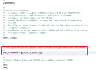
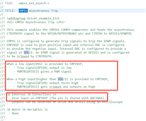
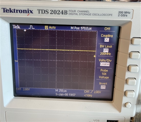
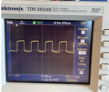
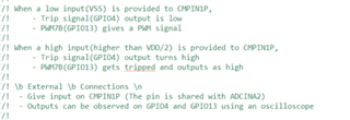
First: Running cmpss on the TMS320F2800137LAUNCHXL development board_ Ex1_ Asynch demo, follow the prompts in the figure below to ground or connect ADCINA2 to 3.3V voltage. PWM7B (GPIO13) does not have PWM signal output. May I ask what and how to achieve this demo function?
Secondly, regarding the AC voltage loop PI algorithm, your company has many PI algorithm functions, as follows: DCL_ RunPI_ C1 (), DCL_ RunPI_ C1 (), DCL_ RunPI_ C2 (), DCL_ RunPI_ C3(), DCL_ RunPI_ C4(), DCL_ RunPI_ C5 (), DCL_ RunPI_ C6 (), DCL_ RunPI_ C7(); May I ask which comparison is an AC voltage loop?
best regards!
yong