Because of the holidays, TI E2E™ design support forum responses will be delayed from Dec. 25 through Jan. 2. Thank you for your patience.

This thread has been locked.

If you have a related question, please click the "Ask a related question" button in the top right corner. The newly created question will be automatically linked to this question.

TMS320F28379D: SPI Boot Mode with External EEPROM interface support needed

Part Number: TMS320F28379D
Other Parts Discussed in Thread: C2000WARE

I have a Controller(TMS320F28379D) and EEPROM(25AA512, spi interface), i was trying to boot this controller with EEPROM in boot mode so that the controller takes the code from EEPROM. can you guide me with the appropriate steps. I have referred the reference manual of the controller section 4.10.4.3 SPI Boot Mode, but the information is not clear.

NOTE : not looking for EEPROM emulation using flash

Best Regards
Saddam  

  • Hi Saddam,

    Just wanted to be sure you are aware that if you hard wire the configuration to use SPI boot mode, the device will use SPI boot every time it powers on or resets and will not boot from flash. 

    - Allison

  • Hi Allison,
    Thanks for the response, and i appreciate the information you provided, but this not what the question is about, 
    Requirement : The hex file inside the EEPROM is to be used by controller in SPI boot mode, so what is the procedure to achieve this.
    Achieved : I have successfully completed the SPI communication with EEPROM using SPI_BOOT.c file, note : used SPIB, but have no information what to do next.

    Best Regards,
    Saddam

  • Hi Saddam, 

    To clarify, do you mean you need help with steps to take besides setting the boot pins to GET mode and configuring the key for SPI Boot mode? You have successfully implemented SPI boot mode and hardware setup but want to know how to send the hex from EEPROM to F2837 via SPI communication?

    Best Regards,

    Allison

  • You have successfully implemented SPI boot mode and hardware setup but want to know how to send the hex from EEPROM to F2837 via SPI communication?

    Hi Allison,

    Yes, please help.

  • Hi Saddam,

    We are not familiar with this specific EEPROM device, but we do have software examples with AT25128/256 that you can use as a reference guide. While F2837xD specifically doesn't have this SPI EEPROM example, F2838x does have it example (spi_ex6_eeprom in C2000Ware) that would be helpful for you to look at for help here. 

    You mentioned earlier that you were able to communicate with EEPROM, so is there a specific part of the communication that you are having issues with? Scoping out the 4 SPI pins can help to check correct communication as well, if you are trying to debug your code.

    Best Regards,

    Allison

  • Hi Allison,


    I don't want help for SPI, i want exact steps for "How to use boot mode via spi"

    Requirement : The hex file inside the EEPROM is to be used by controller in SPI boot mode, so what is the procedure to achieve this.

    please understand what is the requirement(quoted above).

    Best Regards

    Saddam

  • Hi Saddam,

    For the steps to test boot mode via SPI, you can do the following:

    1. Open CCS, view and launch the target configuration file

    2. In the debug window, right click CPU1 and connect to target

    3. Under the view tab, click the memory browser window and input address 0xD00. At this address, type the hex value 0x045A.

    4. In the toolbar pane, click the CPU Reset button for CPU1 and then press the resume button.

    You will have to configure the SPI for your EEPROM so that it is able to be recognized. For more on this, it is better to look at section 4.10.4.3. My expertise is currently not with this peripheral, but can look and see if anything else specific is required, will let you know.

    Thanks and regards,

    Charles

  • 1. Open CCS, view and launch the target configuration file

    => what to do after launching the target configuration file ?

    2. In the debug window, right click CPU1 and connect to target

    3. Under the view tab, click the memory browser window and input address 0xD00. At this address, type the hex value 0x8104.

    => Done successfully

    4. In the toolbar pane, click the CPU Reset button for CPU1 and then press the resume button.

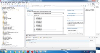
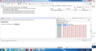
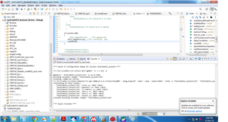
    Now after clicking cpu reset following occurs : 

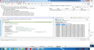
    after clicking resume following occurs:

    I can't see how this is getting me into spi boot mode ?

    Question1) In TRM of TMS320F28x controller, in spi boot mode section 4.10.4.3, can you tell me the steps 1 to 8 are to be coded inside the main function, or before the main function,

    a) if inside the main function then where, just after start of main function or where?

    b) if before the main function then where?

    Question2) And in this steps of section 4.10.4.3 or in TRM, it is not clear how the code/controller is determining which code it should be running, whether from EEPROM or flash\

    Question3) which are the boot pins for spi boot mode : 

    a) It is not clear gpio pins for spi mode, please clear this
    b) And where is the BOOTCTRL register in code, and how to configure it if required

    Question4) can you please provide an example code, because in TRM it is really not clear, how to achieve the task(task : i want to program hex file from external eeprom into the controller, because onsite we don't want to program the controller so we want to put the hex file in external eeprom and simply plug into the pcb and reset the board while adding the jumper pin to boot pins, so the controller should get the updated hex file from eeprom)

  • Hi Saddam,

    I actually have a correction for you, the boot mode should be 0x045A (04 for SPI boot mode, 5A to confirm that the register is valid).   

    Q1a) These steps occur within the Uint32 SPI_Boot(Uint32 Bootmode) function, which is a part of bootROM code (SPI_Boot.c).

    Q1b) Before main, the device is configuring clocks and selects the boot mode.

    Q2) This is determined from the Uint16 SPIA_SetAddress_KeyChk() function. Can look into this for you.

    Q3a) The boot pins for SPI mode are determined by what boot mode is passed into the SPI_Boot function. By default, the boot pins uses are GPIO16, GPIO17, GPIO18, and GPIO19. These relate to the function SPI_Pinmux_Option2(). 

    Q3b) The BOOTCTRL register is referenced in the code in the SelectMode_Boot.c file.

    Q4) My bandwidth is limited right now for this task, will see what can be done.

    Thanks and regards,

    Charles

  • Hi Charles,

    I actually have a correction for you, the boot mode should be 0x045A (04 for SPI boot mode, 5A to confirm that the register is valid).

    I didn't get what you are suggesting in this quoted message, are you asking to update the 0xD00 address with the value 0x045A?

    1) In your previous response you suggested 4 steps for getting into boot mode, of which i have given you the screenshot for the same, please clarify.

    2) As you mentioned the SPI_Boot.c file, but didn't mentioned where to call the functions of that file, inside the main or before the main and where exactly, this information is really missing inside the TRM as well, that is the reason i am asking for basic/simple example code to understand the boot process using spi eeprom, so all my questions are answered.

    3) If you bandwidth is limited please forward someone who ie available

    Best Regards 

    Saddam

  • Hi Saddam,

    Yes, please update the 0xD00 address with 0x045A for SPI Boot Mode. I am reaching out to a few others for support here as well, so please allow for some more time as they get back to me- expect an update before end of tomorrow. I have taken note of this as well so we can work on improving and clarifying our descriptions of SPI boot mode in the future for easier implementation.

    Best Regards,

    Allison

  • Hi Saddam, still waiting to hear back, but I will update again Monday or as soon as I hear back. 

    Best Regards

  • Hi Allison,

    Still waiting for your reply.

    I want to share some steps i have have done and have some questions regarding the same,

    Note: There are two projects of led blinking, a) 300ms led blinking for eeprom b) 100ms led blinking for controller

    A) Dumping hex file in external eeprom

    => 300ms led blinking code (hex file) to be dump inside external eeprom

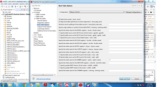
    => Before dumping i have set some settings in properties-> C2000 Hex Utility-> Boot Table Options -> set a) Select boot mode, b) SPI-A port, 8-bit mode(--spi8, -spi8)

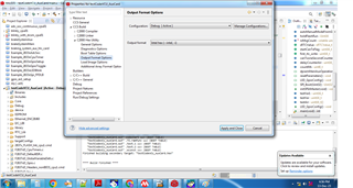
    => Output format Options -> set 'Intel hex'

    => Building the project

    => When reading this hex file, i can see the key = 0x8AA in first two bytes

    B) Standalone Boot

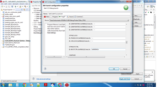
    => Debug Configurations-> Target-> Flash Settings-> Z1-Bootctrl(0x7801e) = 0x0000045A

    => After building -> debug mode

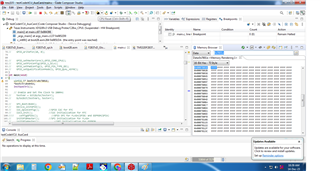
      as you can see the value of z1-bootctrl in memory browser
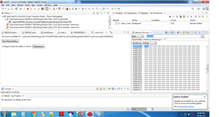
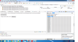
    => CPU Reset

    => Resume

    => Pause

      as you can see the value of bootctrl register is not changed, and the controller code is running instead of eeprom code
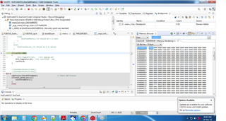
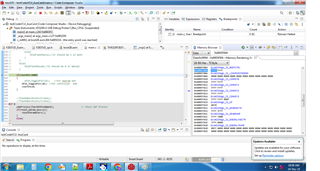
    => You can see Boot Status Registers as well, as there is flash boot in the register value, instead of spi boot

    => I Think the controller is not getting into spi boot, because the address i am setting the value (0x045A) is not wrong address you provided in TRM, because as you can see in memory browser below the address is 0x0005F004 instead of 0x7801e, and if 0x0005F004 is the correcet address for setting the bootctrl register then please tell me how to do it, because in flash settings of target in debug configurations the address is 0x7801e

    => And one more thing do i have to set the other register as well in flash setting, refer below picture

    NOTE: I done power reset my controller board in standalone boot as well, but controller code is running instead of eeprom code
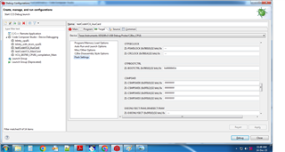
    B) Emulation Mode

    => Setted the value 0x045A in register 0x00d00 in debug mode

    => CPU Reset

    => Resume

    => Pause

    => Even in emulation mode controller code is running instead of eeprom code
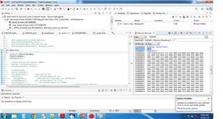
    I am waiting for your reply as soon as possible, am still asking for a example code or any documentation from you.

    Best Regards

    Saddam

  • Hi Saddam,

    Thank you for the information and continued patience. I am still awaiting response, but am reaching out still for more support here. I will update tomorrow on hearing back from them.

    Best Regards,

    Allison

  • Hi Saddam,

    Apologies as I am still waiting to hear back (this is out of my expertise), but I can try to offer some further guidance here:

    The first note would be to stick with using emulation boot mode for now - use this to debug and verify that you can get things working with EEPROM connected properly. Once we confirm that it is set up correctly, then move on to programming OTP using flash tools to set it up.

    There should be a way for you to select EMU boot mode after you set it up as you showed in your screenshots above. First, issue a reset in CCS, then go to the 'Scripts' tab in the tool bar and use the 'EMU Boot Mode Select' functionality. Let me know if you are able to do this and get EMU boot mode working. 

    Best Regards,

    Allison

  • Hi Allison,

    The steps you mention above for emu booting didn't work for me.

    1) In toolbar->Scripts->EMU Boot Mode Select->(EMU_BOOT_SARAM & EMU_BOOT_FLASH), but i want EMU_BOOT_SPI, which is not showed in that option.

    2) Even though i have manually put the value 0x045A on address 0x00d00 in memory browser, in cpu reset state in debug mode, and hit resume, but it runs the controller code and eeprom code. (NOTE: I have already done this and given you the screenshot in previous reply)

    Best Regards

    Saddam

  • Hi Saddam, 

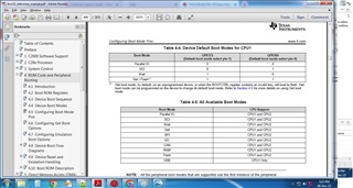
    Thanks for the response. Another item of notice is that earlier in your response, you said you were using SPIB. As per the datasheet, there are two SPI-Boot modes (0 and 1) depending on the which GPIO's you are using - but both are designated for SPIA Boot. (see Table 9-15. GPIO Pins Used by Each Peripheral Bootloader of the datasheet). 

    Some questions in light of this: Which set of GPIOs are you using (I know Charles discussed this with you earlier, but I want to check again and see if you are utilizing SPI Boot 0 and SPI Boot 1). Also, are you still trying to use SPIB? Have you tried using SPIA? If not, please try to implement SPIA here.

    Best Regards,

    Allison

  • Hi Allison

    I am using SPIA (GPIO58, GPIO59, GPIO60, and GPIO61) so according to TRM am using SPI BOOT 0.

    As you can see the screenshot in above response, in debug mode i have set the EMU_BOOTCTRL register(0x0d00) as 0x045A, and here 04 means SPI BOOT 0.

    Best Regards

    Saddam

  • Hi Saddam, 

    It looks like when you resume and the re-pause your program from the screenshots above, this is passed where SPI_Boot.c is actually referenced.

    Below are some instructions to step through the Emulation SPI Boot process give more context as to where SPI_Boot.c is called. This can help to check that you are seeing SPI communication successfully as well.

    1. Open your project in CCS and launch the target configuration file as usual
    2. In the debug window, right click CPU1 and connect to target
    3. Under the view tab, click the memory browser window and input address 0xD00. At this address, enter the hex value 0x045A
    4. In the tool bar, click the 'CPU Reset' button for CPU1
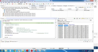
    5. In the tool bar, click the dropdown next to the 'Load' button ( ), and click 'Load Symbols'
    6. In the pop-up, click 'Browse' and select the file at the directory: C2000Ware_5_01_00_00\libraries\boot_rom\f2837xd\revB\rom_sources\ccs_files\cpu01\Release\F2837x_cpu01_bootROM_REVB_Golden_020314.out
    7. After loading that file, a window will pop up saying that CCS cannot find a source file. Click 'Locate File' and select this location: C2000Ware_5_01_00_00\libraries\boot_rom\f2837xd\revB\rom_sources\F2837x_bootROM\cpu01-bootROM\source
    8. The "c1brom_Init_Boot.asm" file will open. Navigate to line 370 ("LCR _c1brom_system_init"). Right click on the line and select 'run to line'.
    9. In the tool bar, click the 'Step Into' button once, and this will open 'c1brom_boot.c' file
    10. Set a break point at line 722: "else if(BootMode == SPI_BOOT|| (BootMode == SPI_BOOT_ALTERNATE)) EntryAddr = SPI_Boot(BootMode);"
    11. From here, you can verify that BootMode is set to SPI_BOOT (0x4) and then use the tool bar button again to 'Step Into' the 'SPI_Boot.c' file
    12. From within 'SPI_Boot.c', you can step through and verify that the SPI connection between the F2837xD and the EEPROM device is behaving as expected.
      1. I would also recommend using an oscilloscope to look at the SPI lines to confirm that the chip select pin is going low and data is being communicated between the two devices.

    Please let me know if you are able to follow these steps and see SPI communication. 

    WARNING: You can only program the OTP boot control key twice, so be sure to verify that everything works in emulation mode before actually programming OTP. You can program the key into OTP using 'Tools' > 'On-Chip Flash'. Scroll down to 'OTPBOOTCTRL' and type it there before pressing the button to program it. But, again, proceed with caution here:

    Best Regards,

    Allison

  • Hi Allison,

    All the steps you mentioned works perfectly fine, and yes i am able to establish the SPI communication between external eeprom and controller, because in SPI_start_Boot() i can see it is reading the key : 0x08AA, which means spi is working and returning the entryAddress(Decimal :545171).

    But when i run resume after getting the entry address, it doesn't run the eeprom code, it still runs the controller code.

    Screenshots for your reference are as follows:

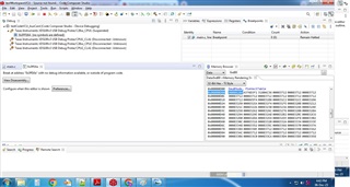
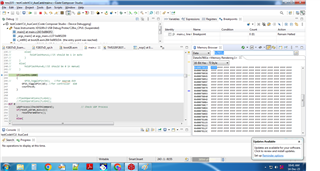
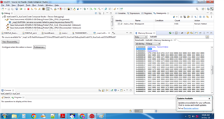
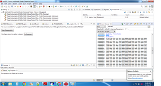
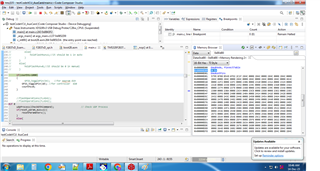
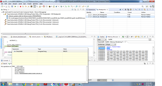
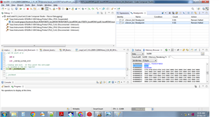
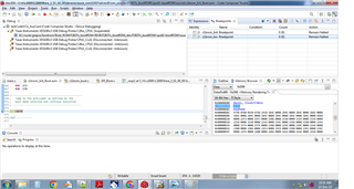
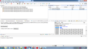
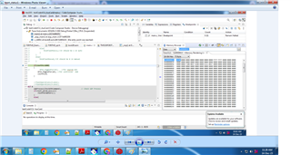
    1)After completing the spi_boot() function which returns entryAddress, and i am going step by step till the exitBoot, and pressing resume, then code goes nowwhere(refer pic 4)):

    1) 2) 3) 4)

    Best Regards,

    Saddam

  • Hi Saddam,

    Thank you for posting the details of stepping through the SPI Boot process, I have a few questions and suggestions. 

    1. Does the entryAddress returned by cpu1brom_system_init() agree with what you see in the Memory Browser? I would expect the application to be programmed at 0x80000, as stated in section 4.10.1 of the Technical Reference Manual. Is the 0x80000 address occupied by other data? If so, please use the On-Chip Flash tool to erase Flash memory before programming. 

    2. I noticed that you used the Intel Hex format when generating the hex file for the LED blinking application. Please use the ASCII Hex output format (-a or --ascii) to generate the hex file. See section 4.10.5 of the Technical Reference Manual for more details.

    3. I am not sure I understand what behavior you are seeing after the application is loaded into Flash. Earlier you said that it runs the controller code instead of the EEPROM code, but in the screenshots you mentioned that it doesn't go anywhere. What controller code is running? Are you loading a program onto the controller before SPI_Boot takes place? 

    Kind regards,

    Skyler

  • Hi Skyler,

    1) You can see in the screenshot, the address is 0x00085193, this occured when i followed allison steps

    2)It should be intel hex(i think), because when i read the ASCII hex file i don't see the key (0x08AA) on first two bytes and later on, but i can see the key and other things like baudrate in intel hex file.

    ASCII Hex file

    Intel Hex file

    3) You can see in the screen shot in my above response, In Debug Mode i can see my code running that is led blinking, but when i pause the program then that nowwhere thing appears(refer the screenshot in previous response Pic 4).

    Best Regards

    Saddam

  • Hi Saddam, 

    Skyler and several other experts are currently out of office expected to return Jan. 2. But I believe ASCII is the correct format that should be used, so there may be an issue there- I am checking on this to confirm. How are you generating these files?

    Best Regards,

    Allison

  • Hi Saddam,

    If the LED is blinking in debug, then your application code appears to be running. When you pause it and it "goes nowhere" this could indicate that you need to load the correct symbols (in a similar manner as you did before in debugging the SPI_Boot.c), so when you pause it, try loading the .out file of your project's code. Let me know if this changes what you are able to see- this should show that the code loaded from EEPROM is running. Note that this step is not necessary for the code to run, but it is necessary for you to be able to view it in debug mode. 

    Could you also please send the led blinky project application .cmd file so I can check the addresses there as well?

    Best Regards,

    Allison

  • Hi Allison,

    I am generating the output files, by setting the output format in properties->c2000 Hex Utility-> Output Format Options and building the project, then the hex file is generated.

    1) can you tell whether what should be the 'EntryAddress' after the spi_boot is completed, which is at the boot exit.

    2) you want me to do this step after the boot is completed, i.e when the code is at boot exit or at the cpu reset?

    so when you pause it, try loading the .out file of your project's code.

    3) i think the loading of symbols is correct, that is the reason the code is running the spi boot functions, and if not then please tell me how to do it in correct way.

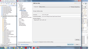
    4) i was not able to send you the .cmd file, hence i have provided the screenshot of the content of the file.

    fig1) fig2)

    fig3) fig4)

    Best Regards,

    Saddam

  • Hi Saddam,

    1. Based on the hex file and .cmd file you provided, the Entry Address returned by SPI Boot looks correct. Can you send the contents of "Summary of flags set:" when you navigate to Properties -> C2000 Hex Utility in the LED Blinky project?

    2. I believe the reason that you are seeing the code go nowhere after pausing is because the symbols of the LED Blinky application are not loaded. Thus, when you pause the debug session after the LED starts blinking, you will not be able to see source code running on the device. To load the symbols, pause the debug session after the LED application has successfully been loaded, navigate to "Load Symbols", and select the .out file corresponding to the LED Blinky application project

    Kind regards,

    Skyler

  • Hi Skyler,

    first let me clear that there are two codes : one for eeprom(led blink 300ms) and other for controller(led blink 1s).

    1) I have programmed the controller via controller code and set in debug mode, then done cpu reset and then loaded symbols : "C:\ti\c2000\C2000Ware_2_01_00_00\libraries\boot_rom\f2837xd\revB\rom_sources\ccs_files\cpu01\Release\F2837x_cpu01_bootROM_REVB_Golden_020314.out", and done further steps as guided from Allison in above messages.

    2) 

    To load the symbols, pause the debug session after the LED application has successfully been loaded, navigate to "Load Symbols", and select the .out file corresponding to the LED Blinky application project

    I didn't get by what you mean in this quoted message, do you want me to load the .out file of eeprom code or controller code?

    3)

    Best Regards

    Saddam

  • Hi Saddam,

    Based on my understanding of your use-case, you will need to implement an SPI Flash Kernel to copy the EEPROM code into flash memory. The SPI bootloader loads the EEPROM code into RAM, not flash. I believe this is why you are seeing the controller code continue to run after SPI Boot is completed. The entry address returned by SPI_Boot is determined by the linker command file (.cmd) in the project that builds the EEPROM code. From your screenshots, we can see that the .cmd file is attempting to store the application in flash memory, so that is why it returns a flash entry address despite the SPI_Boot function loading the program into RAM. Based on the behavior you described, the previously loaded controller code in flash must have the same entry address, so it continues to run the controller code.

    In order to implement the desired behavior, a flash kernel will have to be used. The flash kernel is responsible for erasing the previous controller code, receiving the EEPROM application code, and programming the EEPROM code to flash memory by using the Flash API. The general flow of this process is as follows:

    1. Reset the device and use SPI Boot mode
    2. Transfer the flash kernel from EEPROM to the controller via SPI
    3. Flash kernel will take control after SPI Boot is complete
      1. Make sure that the .cmd file corresponding to the flash kernel is configured to be stored and run from RAM
    4. The kernel will erase the old application code from flash memory on the controller
    5. Kernel will configure an SPI connection with EEPROM and receive the new application code
    6. Kernel will write the newly received application code to flash memory and transfer control to it
    7. Newly received code from EEPROM will execute

    For reference, an SCI Flash Kernel for F2837xD is available at C2000Ware_Install_Location/device_support/f2837xd/examples/dual/F2837xD_sci_flash_kernels. (I noticed that you are using C2000Ware v2.01, while the most recent version is C2000Ware v5.01. If the location I previously mentioned is not found, try upgrading to v5.01). This will need to be adapted to function with the SPI peripheral. The bootROM code located at C2000Ware_Install_Location/libraries/boot_rom/f2837xd/revB/rom_sources/f2837x_bootROM/cpu01-bootROM/source is essential for creating the flash kernel. The SPI flash kernel should use a lot of the bootROM code (located at C2000Ware_Install_Location/libraries/boot_rom/f2837xd/revB/rom_sources/f2837x_bootROM/cpu01-bootROM/source/SPI_Boot.c) to accomplish this task. This application note discusses the implementation of the SCI flash kernel (https://www.ti.com/lit/sprabv4) for a few other devices, but the main ideas will be useful for understanding/implementing the SPI flash kernel.

    Please let me know if anything is unclear.

    Kind regards,

    Skyler

  • Hi Skyler,

    I don't understand why I have to do these extra steps, if I have to do this, then what is the use of spi boot mode(I mean, I was under the impression that when I use spi boot mode for EEPROM, then the code from EEPROM is copied in flash address(0x800000 or some other area in flash) and then that address is called from boot exit), if I am wrong please tell what is the use if spi boot?.

    I was thinking that emulation mode will be straightforward but it is getting more complicated.

    Can you tell me the steps for standalone mode for spi boot for EEPROM?

    Best Regards

    Saddam

  • Hi Saddam,

    The SPI Boot mode and corresponding bootloader code are able to load the application into RAM, not flash memory. If you would like to copy the application to flash, you need an SPI flash kernel as described above. Please note that this holds true in both emulation boot and standalone boot. I will reach out to you offline to schedule a meeting if you would like to discuss this further.

    Kind regards,

    Skyler

  • Hi Skyler,

    So suppose I want to copy the code from external EEPROM to RAM instead of Flash, so what do I have to do?

    Best Regards

    Saddam

  • Hi Saddam,

    If you want to copy the code from external EEPROM to RAM, you can follow the steps for Emulation SPI Boot that we have discussed earlier. Be sure that the active configuration of the code stored in EEPROM is targeting RAM. If done correctly, bootloader code and newly generated hex file will load the code directly into RAM. The entryAddress returned by SPI_Boot will indicate that the program has been loaded to RAM, and you should see the new code from EEPROM start to run. 

    Kind regards,

    Skyler

  • Hi Skyler,

    1) I can run the EEPROM code in standalone and emulation mode, by changing flash.cmd to ram.cmd file in 'linker command file', but these were the led_blinky code which is small in code size, but my application code is much larger and is not fitted in RAM, so I have to use the flash kernel, which you suggested earlier.

    2) can you please explain these steps more clearly : 

    • Reset the device and use SPI Boot mode
    • Transfer the flash kernel from EEPROM to the controller via SPI
    • Flash kernel will take control after SPI Boot is complete
      1. Make sure that the .cmd file corresponding to the flash kernel is configured to be stored and run from RAM
    • The kernel will erase the old application code from flash memory on the controller
    • Kernel will configure an SPI connection with EEPROM and receive the new application code
    • Kernel will write the newly received application code to flash memory and transfer control to it
    • Newly received code from EEPROM will execute

    3) can you provide any document regarding the use of the flash kernel, I can't find it in TRM.

    4) I am a bit confused, weather how to use the 'sci flash kernel' and 'spi_boot.c' for my spi boot, to load the code from eeprom to flash.

    For reference, an SCI Flash Kernel for F2837xD is available at C2000Ware_Install_Location/device_support/f2837xd/examples/dual/F2837xD_sci_flash_kernels. (I noticed that you are using C2000Ware v2.01, while the most recent version is C2000Ware v5.01. If the location I previously mentioned is not found, try upgrading to v5.01). This will need to be adapted to function with the SPI peripheral. The bootROM code located at C2000Ware_Install_Location/libraries/boot_rom/f2837xd/revB/rom_sources/f2837x_bootROM/cpu01-bootROM/source is essential for creating the flash kernel. The SPI flash kernel should use a lot of the bootROM code (located at C2000Ware_Install_Location/libraries/boot_rom/f2837xd/revB/rom_sources/f2837x_bootROM/cpu01-bootROM/source/SPI_Boot.c) to accomplish this task. This application note discusses the implementation of the SCI flash kernel (https://www.ti.com/lit/sprabv4) for a few other devices, but the main ideas will be useful for understanding/implementing the SPI flash kernel.

    Best Regards,

    Saddam

  • Hi Saddam,

    Thank you for the questions, we will discuss this more offline and update the thread after.

    Kind regards,

    Skyler