Part Number: TMS320F280025C
Other Parts Discussed in Thread: C2000WARE, UNIFLASH
Hi,
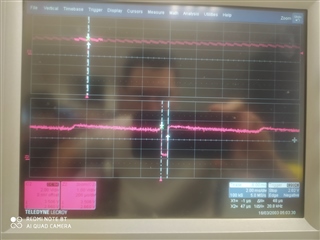
I have a problem with the watchdog reset, I have configured it to trigger a target reset. In my initialization phase, I turn on and off a led to visualize my passage through this phase. The reset is set to a time of 419ms. I also have an ADC interrupt configured for my application, but when I don't reset the counter, I can see the RST pin go to 0, proof that the reset has taken place (duration 50µs at low state). However, I don't revisit my initialization toogle led, so the reboot doesn't work. So I'm missing an element of understanding. Can you please help me?
In another test phase, when I use the ServiceDog() function to reset the counter in my main loop, I only go through the interrupt once, but I still stop in my main loop. The counter increments WDCNTR and is reset to 0 when the servicedog function updates the WDKEY register. So that's strange too. What's the problem, please?
Here myvoid init_watchdog(void)
{
// Reset the watchdog counter
ServiceDog();
// Configure timings to set reset for software watchdog, PREDIVCLK = INTOSC1 / Pre-divider and WDCLK = PREDIVCLK / Prescaler
// With INTOSC1 = 10 MHz, WDCLK = 2441.4 / 4 = 610.35 Hz, 1 tick -> 1/610.35 = 1.638ms and counter is on 8 bits so 256 ticks -> 419 ms
// XRS pin is low for 512 OSCCLK cycles so 512 * (1 / 10.10^6) = 51µs
// Pre-divider = 4096
EALLOW;
//WdRegs.WDCR.bit.WDCHK = 0x5
//WdRegs.WDCR.bit.WDPRECLKDIV = 0x3
// Prescaler = 4
//WdRegs.WDCR.bit.WDPS = 0x3
WdRegs.WDCR.all = 0x032B;
// Counter expiration triggers a reset, this is the default state on the power-up and after any system reset.
// Write to the whole SCSR register to avoid clearing WDOVERRIDE bit
WdRegs.SCSR.all = 0;
EDIS;
}
#pragma CODE_SECTION(adc_isr, ".TI.ramfunc");
__interrupt void adc_isr()
{
    EALLOW;


    // Clear INT1 flag.
    AdccRegs.ADCINTFLGCLR.bit.ADCINT1 = 1;
    // Check if overflow has occurred.
    if(AdccRegs.ADCINTOVF.bit.ADCINT1 == 1)
    {
        // Clear INT1 overflow flag
        AdccRegs.ADCINTOVFCLR.bit.ADCINT1 = 1;
        // Clear INT1 flag
        AdccRegs.ADCINTFLGCLR.bit.ADCINT1 = 1;
    }
    // Acknowledge PIE group 1 to receive more interrupts from this group.
    PieCtrlRegs.PIEACK.bit.ACK1 = 1;
    EDIS;
}
code :int main(void)
{
// PLL initialization and load the code in flash memory by the pre defined symbols include in Project -> Properties -> Pre defined symbols _FLASH to execute the flash initialization.\n
// MemCpy to copy the code in RAM.
InitSysCtrl();
    // Read reset cause register to know which reset is the cause (external or software watchdog)
    if(CpuSysRegs.RESC.bit.WDRSn == true)
    {
        // Indicates reset cause : software
        reset_status = 1;
        // Reset flag in cause register
        CpuSysRegs.RESCCLR.bit.WDRSn = true;
    }
    else if(CpuSysRegs.RESC.bit.XRSn == true)
    {
        // Indicates reset cause : external watchdog
        reset_status = 2;
        // Reset flag in cause register
        CpuSysRegs.RESCCLR.bit.XRSn = true;
    }
// GPIO initialization
gpio_init();
GpioCtrlRegs.GPAPUD.bit.GPIO8 = 1; // Disable the pullup on GPIO8
GpioCtrlRegs.GPADIR.bit.GPIO8 = 1; // GPIO8 = output
GpioCtrlRegs.GPAODR.bit.GPIO8 = 0; // Normal output not open drain
GpioCtrlRegs.GPAQSEL1.bit.GPIO8 = 0; // Synchronous
GpioCtrlRegs.GPAMUX1.bit.GPIO8 = 0; // GPIO8 = GPIO8
GpioDataRegs.GPASET.bit.GPIO8 = 0; // Force output data latch to high level.
GpioDataRegs.GPADAT.bit.GPIO8 = 0; // Set output value
GpioDataRegs.GPADAT.bit.GPIO8 = 1; // Set output value
DELAY_US(2000000);
GpioDataRegs.GPADAT.bit.GPIO8 = 0; // Set output value
// Disable CPU interrupts.
DINT;
// Initialize the PIE control registers to their default value.
InitPieCtrl();
// Disable CPU interrupts and clear all cPU interrupt flags.
IER = 0x0000;
IFR = 0x0000;
// Initialize the PIE vectors table with pointers to the shell Interrupt Service Routine.
InitPieVectTable();
// Authorize register access.
EALLOW;
// Mapping adc_isr function to ADCC_I NT interrupt.
PieVectTable.ADCC1_INT = &adc_isr;
// Lock register access.
EDIS;
// Authorize register access.
EALLOW;
// Mapping tripzone_isr function to EPWM1_TZ_INT interrupt.
PieVectTable.EPWM1_TZ_INT = &tripzone_isr;
// Lock register access.
EDIS;
// Enable group 1 interrupts for ADCC interrupt and WAKE interrupt.
IER |= M_INT1;
// Enable group2 interrupts for trip zone interrupt.
IER |= M_INT2;
// Enable the PIE block
PieCtrlRegs.PIECTRL.bit.ENPIE = 1;
// Enable PIE interrupt 1.3 for ADCC1 interrupt.
PieCtrlRegs.PIEIER1.bit.INTx3 = 1;
// Enable PIE interrupt 2.1 for EPWM1 trip zone interrupt.
PieCtrlRegs.PIEIER2.bit.INTx1 = 1;
// Read master/slave configuration pin to initialize PWM correctly with phase shift equal 60° between them
if(GpioDataRegs.GPADAT.bit.GPIO12 == false)
{
uc_state_master_slave = MASTER;
// EPWM initialization function.
epwm_init_spwm_branch_u();
epwm_init_spwm_branch_v();
epwm_init_spwm_branch_w();
// Configure synchronization signal : load program to uC1 firstly because uC2 need external synchronization
epwm_synch_init();
}
else
{
uc_state_master_slave = SLAVE;
epwm_init_spwm_branch_x();
epwm_init_spwm_branch_y();
epwm_init_spwm_branch_z();
}
// Software watchdog initialization
init_watchdog();
// Analog to Digital Converter initialization.
adc_init();
// Comparator subsytem initialization.
// Fuel cell OVP and Battery OCP
cmpss1_init();
// Battery OVP and Mi_U peak current
cmpss2_init();
// Mi_W peak current
cmpss3_init();
// MI_V peak current
cmpss4_init();
// Configure trip zone for return driver (GPIOmux -> InputXbar -> Trip_zone -> Epwm_module)
tz_driver_return_init();
// CPUTimer2 is used for extern watchdog.
init_cpu_timers(&CpuTimer2Regs);
// CAN bus initialization
can_init();
// I2C bus initialization
i2c_init();
// Reset timer
CpuTimer2Regs.TCR.bit.TRB = 1;
// Enable Global interrupt INTM
EINT;
// Enable Global realtime interrupt DBGM
ERTM;
while(1)
{
// Extern watchdog (200ms)
// Toggle pin for watchdog for WDI signal on TPS3823-33Q1
level_wdi_watchdog_pin = !level_wdi_watchdog_pin;
GpioDataRegs.GPADAT.bit.GPIO25 = level_wdi_watchdog_pin;
extern_watchdog_meas.start_time = CpuTimer2Regs.TIM.all;
// Reset the watchdog counter
ServiceDog();
extern_watchdog_meas.end_time = CpuTimer2Regs.TIM.all;
// Measure main loop timing
extern_watchdog_meas.timediff = extern_watchdog_meas.start_time - extern_watchdog_meas.end_time;
// Reset timer
CpuTimer2Regs.TCR.bit.TRB = 1;
}
}
Thanks
Damien