Hello TI Community,
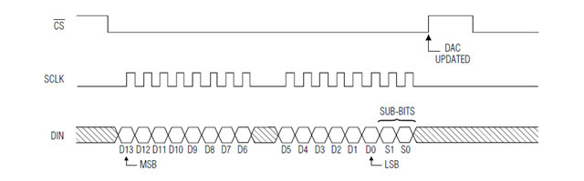
I'm experiencing an issue with the MAX1978 on a development board, where it doesn't respond to SPI transmissions from a C2000 MCU. I'm using a MAX5144 DAC for the SPI-DAC conversion. I've sent a fixed test value calculated as uint16_t fixedData = (uint16_t)(0.3 * 16383), considering the 14-bit resolution of MAX5144.
//#############################################################################
//
// FILE:   spi_ex3_external_loopback_fifo_interrupt.c
//
// TITLE:  SPI Digital Loopback with FIFO Interrupts
//
//! \addtogroup driver_example_list
//! <h1>SPI Digital External Loopback with FIFO Interrupts</h1>
//!
//! This program uses the external loopback between two SPI modules. Both
//! the SPI FIFOs and their interrupts are used. SPIA is configured as a slave
//! and receives data from SPI B which is configured as a master.
//!
//! A stream of data is sent and then compared to the received stream.
//! The sent data looks like this: \n
//!  0000 0001 \n
//!  0001 0002 \n
//!  0002 0003 \n
//!  .... \n
//!  FFFE FFFF \n
//!  FFFF 0000 \n
//!  etc.. \n
//! This pattern is repeated forever.
//!
//! \b External \b Connections \n
//!  -GPIO25 and GPIO17 - SPISOMI
//!  -GPIO24 and GPIO16 - SPISIMO
//!  -GPIO27 and GPIO19 - SPISTE
//!  -GPIO26 and GPIO18 - SPICLK
//!
//! \b Watch \b Variables \n
//!  - \b sData - Data to send
//!  - \b rData - Received data
//!  - \b rDataPoint - Used to keep track of the last position in the receive
//!    stream for error checking
//!
//
//#############################################################################
//
// $Release Date: $
// $Copyright:
// Copyright (C) 2013-2023 Texas Instruments Incorporated - http://www.ti.com/
//
// Redistribution and use in source and binary forms, with or without
// modification, are permitted provided that the following conditions
// are met:
//
//   Redistributions of source code must retain the above copyright
//   notice, this list of conditions and the following disclaimer.
//
//   Redistributions in binary form must reproduce the above copyright
//   notice, this list of conditions and the following disclaimer in the
//   documentation and/or other materials provided with the
//   distribution.
//
//   Neither the name of Texas Instruments Incorporated nor the names of
//   its contributors may be used to endorse or promote products derived
//   from this software without specific prior written permission.
//
// THIS SOFTWARE IS PROVIDED BY THE COPYRIGHT HOLDERS AND CONTRIBUTORS
// "AS IS" AND ANY EXPRESS OR IMPLIED WARRANTIES, INCLUDING, BUT NOT
// LIMITED TO, THE IMPLIED WARRANTIES OF MERCHANTABILITY AND FITNESS FOR
// A PARTICULAR PURPOSE ARE DISCLAIMED. IN NO EVENT SHALL THE COPYRIGHT
// OWNER OR CONTRIBUTORS BE LIABLE FOR ANY DIRECT, INDIRECT, INCIDENTAL,
// SPECIAL, EXEMPLARY, OR CONSEQUENTIAL DAMAGES (INCLUDING, BUT NOT
// LIMITED TO, PROCUREMENT OF SUBSTITUTE GOODS OR SERVICES; LOSS OF USE,
// DATA, OR PROFITS; OR BUSINESS INTERRUPTION) HOWEVER CAUSED AND ON ANY
// THEORY OF LIABILITY, WHETHER IN CONTRACT, STRICT LIABILITY, OR TORT
// (INCLUDING NEGLIGENCE OR OTHERWISE) ARISING IN ANY WAY OUT OF THE USE
// OF THIS SOFTWARE, EVEN IF ADVISED OF THE POSSIBILITY OF SUCH DAMAGE.
// $
//#############################################################################

//
// Included Files
//
#include "driverlib.h"
#include "device.h"

//
// Globals
//
volatile uint16_t sData[2];         // Send data buffer
volatile uint16_t rData[2];         // Receive data buffer
volatile uint16_t rDataPoint = 0;   // To keep track of where we are in the
                                    // data stream to check received data

//
// Function Prototypes
//
void initSPIBMaster(void);
void initSPIASlave(void);
void configGPIOs(void);
__interrupt void spibTxFIFOISR(void);
__interrupt void spiaRxFIFOISR(void);

//
// Main
//
void main(void)
{
    uint16_t i;

    //
    // Initialize device clock and peripherals
    //
    Device_init();

    //
    // Disable pin locks and enable internal pullups.
    //
    Device_initGPIO();

    //
    // Initialize PIE and clear PIE registers. Disables CPU interrupts.
    //
    Interrupt_initModule();

    //
    // Initialize the PIE vector table with pointers to the shell Interrupt
    // Service Routines (ISR).
    //
    Interrupt_initVectorTable();

    //
    // Interrupts that are used in this example are re-mapped to ISR functions
    // found within this file.
    //
    Interrupt_register(INT_SPIB_TX, &spibTxFIFOISR);
    Interrupt_register(INT_SPIA_RX, &spiaRxFIFOISR);

    //
    // Configure GPIOs for external loopback.
    //
    configGPIOs();

    //
    // Set up SPI B as master, initializing it for FIFO mode
    //
    initSPIBMaster();

    //
    // Set up SPI A as slave, initializing it for FIFO mode
    //
    initSPIASlave();

    //
    // Initialize the data buffers
    //
    for(i = 0; i < 2; i++)
    {
        sData[i] = i;
        rData[i]= 0;
    }

    //
    // Enable interrupts required for this example
    //
    Interrupt_enable(INT_SPIA_RX);
    Interrupt_enable(INT_SPIB_TX);

    //
    // Enable Global Interrupt (INTM) and realtime interrupt (DBGM)
    //
    EINT;
    ERTM;

    //
    // Loop forever. Suspend or place breakpoints to observe the buffers.
    //
    while(1)
    {
        ;
    }
}

//
// Function to configure SPI B as master with FIFO enabled.
//
void initSPIBMaster(void)
{
    //
    // Must put SPI into reset before configuring it
    //
    SPI_disableModule(SPIB_BASE);

    //
    // SPI configuration. Use a 500kHz SPICLK and 16-bit word size.
    //
    SPI_setConfig(SPIB_BASE, DEVICE_LSPCLK_FREQ, SPI_PROT_POL0PHA0,
                  SPI_MODE_MASTER, 500000, 16);
    SPI_disableLoopback(SPIB_BASE);
    SPI_setEmulationMode(SPIB_BASE, SPI_EMULATION_FREE_RUN);

    //
    // FIFO and interrupt configuration
    //
    SPI_enableFIFO(SPIB_BASE);
    SPI_clearInterruptStatus(SPIB_BASE, SPI_INT_TXFF);
    SPI_setFIFOInterruptLevel(SPIB_BASE, SPI_FIFO_TX2, SPI_FIFO_RX2);
    SPI_enableInterrupt(SPIB_BASE, SPI_INT_TXFF);

    //
    // Configuration complete. Enable the module.
    //
    SPI_enableModule(SPIB_BASE);
}

//
// Function to configure SPI A as slave with FIFO enabled.
//
void initSPIASlave(void)
{
    //
    // Must put SPI into reset before configuring it
    //
    SPI_disableModule(SPIA_BASE);

    //
    // SPI configuration. Use a 500kHz SPICLK and 16-bit word size.
    //
    SPI_setConfig(SPIA_BASE, DEVICE_LSPCLK_FREQ, SPI_PROT_POL0PHA0,
                  SPI_MODE_SLAVE, 500000, 16);
    SPI_disableLoopback(SPIA_BASE);
    SPI_setEmulationMode(SPIA_BASE, SPI_EMULATION_FREE_RUN);

    //
    // FIFO and interrupt configuration
    //
    SPI_enableFIFO(SPIA_BASE);
    SPI_clearInterruptStatus(SPIA_BASE, SPI_INT_RXFF);
    SPI_setFIFOInterruptLevel(SPIA_BASE, SPI_FIFO_TX2, SPI_FIFO_RX2);
    SPI_enableInterrupt(SPIA_BASE, SPI_INT_RXFF);

    //
    // Configuration complete. Enable the module.
    //
    SPI_enableModule(SPIA_BASE);
}

//
// Configure GPIOs for external loopback.
//
void configGPIOs(void)
{
    //
    // This test is designed for an external loopback between SPIA
    // and SPIB.
    // External Connections:
    // -GPIO25 and GPIO17 - SPISOMI
    // -GPIO24 and GPIO16 - SPISIMO
    // -GPIO27 and GPIO19 - SPISTE
    // -GPIO26 and GPIO18 - SPICLK
    //

    //
    // GPIO17 is the SPISOMIA.
    //
    GPIO_setMasterCore(17, GPIO_CORE_CPU1);
    GPIO_setPinConfig(GPIO_17_SPISOMIA);
    GPIO_setPadConfig(17, GPIO_PIN_TYPE_PULLUP);
    GPIO_setQualificationMode(17, GPIO_QUAL_ASYNC);

    //
    // GPIO16 is the SPISIMOA clock pin.
    //
    GPIO_setMasterCore(16, GPIO_CORE_CPU1);
    GPIO_setPinConfig(GPIO_16_SPISIMOA);
    GPIO_setPadConfig(16, GPIO_PIN_TYPE_PULLUP);
    GPIO_setQualificationMode(16, GPIO_QUAL_ASYNC);

    //
    // GPIO19 is the SPISTEA.
    //
    GPIO_setMasterCore(19, GPIO_CORE_CPU1);
    GPIO_setPinConfig(GPIO_19_SPISTEA);
    GPIO_setPadConfig(19, GPIO_PIN_TYPE_PULLUP);
    GPIO_setQualificationMode(19, GPIO_QUAL_ASYNC);

    //
    // GPIO18 is the SPICLKA.
    //
    GPIO_setMasterCore(18, GPIO_CORE_CPU1);
    GPIO_setPinConfig(GPIO_18_SPICLKA);
    GPIO_setPadConfig(18, GPIO_PIN_TYPE_PULLUP);
    GPIO_setQualificationMode(18, GPIO_QUAL_ASYNC);

    //
    // GPIO25 is the SPISOMIB.
    //
    GPIO_setMasterCore(25, GPIO_CORE_CPU1);
    GPIO_setPinConfig(GPIO_25_SPISOMIB);
    GPIO_setPadConfig(25, GPIO_PIN_TYPE_PULLUP);
    GPIO_setQualificationMode(25, GPIO_QUAL_ASYNC);

    //
    // GPIO24 is the SPISIMOB clock pin.
    //
    GPIO_setMasterCore(24, GPIO_CORE_CPU1);
    GPIO_setPinConfig(GPIO_24_SPISIMOB);
    GPIO_setPadConfig(24, GPIO_PIN_TYPE_PULLUP);
    GPIO_setQualificationMode(24, GPIO_QUAL_ASYNC);

    //
    // GPIO27 is the SPISTEB.
    //
    GPIO_setMasterCore(27, GPIO_CORE_CPU1);
    GPIO_setPinConfig(GPIO_27_SPISTEB);
    GPIO_setPadConfig(27, GPIO_PIN_TYPE_PULLUP);
    GPIO_setQualificationMode(27, GPIO_QUAL_ASYNC);

    //
    // GPIO26 is the SPICLKB.
    //
    GPIO_setMasterCore(26, GPIO_CORE_CPU1);
    GPIO_setPinConfig(GPIO_26_SPICLKB);
    GPIO_setPadConfig(26, GPIO_PIN_TYPE_PULLUP);
    GPIO_setQualificationMode(26, GPIO_QUAL_ASYNC);
}

//
// SPI A Transmit FIFO ISR
//
/*__interrupt void spibTxFIFOISR(void)
{
    uint16_t i;

    //
    // Send data
    //
    for(i = 0; i < 2; i++)
    {
       SPI_writeDataNonBlocking(SPIB_BASE, sData[i]);
    }

    //
    // Increment data for next cycle
    //
    for(i = 0; i < 2; i++)
    {
       sData[i] = sData[i] + 1;
    }

    //
    // Clear interrupt flag and issue ACK
    //
    SPI_clearInterruptStatus(SPIB_BASE, SPI_INT_TXFF);
    Interrupt_clearACKGroup(INTERRUPT_ACK_GROUP6);
}*/

__interrupt void spibTxFIFOISR(void)
{
    uint16_t i;

    // 计算DAC的固定值,例如0.3的比例
    uint16_t fixedData = (uint16_t)(0.3 * 16383); // 16383 = 2^14 - 1
    uint8_t highByte, lowByte;

    // 从16位数据中提取两个8位字节
    highByte = (fixedData >> 8) & 0xFF; // 高8位
    lowByte = fixedData & 0xFF;        // 低8位

    // 发送数据
    for(i = 0; i < 2; i++)
    {
        // 发送高8位
        SPI_writeDataNonBlocking(SPIB_BASE, highByte);

        // 发送低8位
        SPI_writeDataNonBlocking(SPIB_BASE, lowByte);
    }

    // Increment data for next cycle - 但在这里我们不修改数据,因为我们发送固定的值
    for(i = 0; i < 2; i++)
    {
       // 在这里不需要修改sData,因为我们总是发送相同的固定值
    }

    // 清除中断标志并确认
    SPI_clearInterruptStatus(SPIB_BASE, SPI_INT_TXFF);
    Interrupt_clearACKGroup(INTERRUPT_ACK_GROUP6);
}


//
// SPI B Receive FIFO ISR
//
 __interrupt void spiaRxFIFOISR(void)
{
    uint16_t i;

    //
    // Read data
    //
    for(i = 0; i < 2; i++)
    {
        rData[i] = SPI_readDataNonBlocking(SPIA_BASE);
    }

    //
    // Check received data
    //
    for(i = 0; i < 2; i++)
    {
        if(rData[i] != (rDataPoint + i))
        {
            // Something went wrong. rData doesn't contain expected data.
            Example_Fail = 1;
            ESTOP0;
        }
    }

    rDataPoint++;

    //
    // Clear interrupt flag and issue ACK
    //
    SPI_clearInterruptStatus(SPIA_BASE, SPI_INT_RXFF);
    Interrupt_clearACKGroup(INTERRUPT_ACK_GROUP6);

    Example_PassCount++;
}

//
// End of File
//MAX5141-MAX5144.pdf8422.max1978evkit.pdf those datasheet for MAX1978 and MAX5144
The SPI output appears correct, but the MAX1978 doesn't respond as expected, particularly in terms of TEC temperature control. I anticipated the TEC would heat up corresponding to the 0.3 DAC value. Could anyone offer insights or troubleshooting suggestions for this issue?
Thanks in advance!
Nero


 I did this, after change it no more signal now lol