This thread has been locked.

If you have a related question, please click the "Ask a related question" button in the top right corner. The newly created question will be automatically linked to this question.

Interface between F28069 and I2C EEPROM

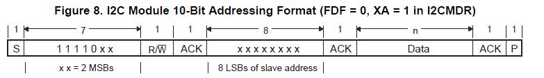
I am trying to use the I2C Module 10-bit Addressing Format to connect to an I2C EEPROM M24C08.

However, the device type identifier bits generated by the DSP is 11110xx (first 7-bits after a START condition) and the one expected by the I2C EEPROM is 10100xx. The device identifier of the EEPROM is the same for all manufacturers. How can I change the device identifier generated by the DSP ?

Thank you

Denise

  • Hi Denise,

    This is an I2C standard for 10-bit addressing. I do not think this can be changed. 10-bit addressing is handled a little bit differently than 7-bit as the master sends the slave address in two separate byte transfers.  I am attaching an excerpt from our I2C Reference Guide:

    http://www.ti.com/litv/pdf/sprufz9d

    10-Bit Addressing Format
    The 10-bit addressing format (see Figure 8) is similar to the 7-bit addressing format, but the master sends
    the slave address in two separate byte transfers. The first byte consists of 11110b, the two MSBs of the
    10-bit slave address, and R/W = 0 (write). The second byte is the remaining 8 bits of the 10-bit slave
    address. The slave must send acknowledgment after each of the two byte transfers. Once the master has
    written the second byte to the slave, the master can either write data or use a repeated START condition
    to change the data direction. For more details about using 10-bit addressing, see the Philips
    Semiconductors I2C-bus specification.


    To select the 10-bit addressing format, write 1 to the XA bit of I2CMDR and make sure the free data
    format mode is off (FDF = 0 in I2CMDR).

    Regards,
    Patrick

  • Denise,

    The first 5 bits after the start bit can't be changed.  I2C BOOT ROM should actually be configured as slave, so 8LSB's of slave address should be entered after ACK bit and 2 MSB's should be entered before R/W bit as shown below.


    Hope this helps.

    Regards,

    Manoj

  • Hi Patrick,

    If the device identifier can not be changed on the DSP side, could you please suggest a I2C EEPROM part number that has the device identifier 11110b ?

    I found only I2C EEPROM with device identifier 10100, as the ones I am attaching the datasheets. 8688.PCA24S08.pdf6622.CD00001163.pdf

    Thank you for your attention.

    Regards,

    Denise

  • Denise,

    11110b is not the device identifier. This is just the structure of the message passing for 10-bit addressing. The process of 10-bit addressing is handled differently. The master sends the slave address in two separate bytes. The first bytes consists of 11110b AND the two most significant bits of the slave address. The second byte consists of the remaining 8 bits of the slave address. The last two bits of the first byte and the 8 bits of the second byte are concatenated to form the 10 bit slave address.

    However you are correct, per the Philips I2C specification, the key point seems to be that you cannot use a 7-bit slave in a 10-bit addressing format. Thus,you will need to address it with a 7-bit address format (unless you find a 10-bit addressable EEPROM). However, note that 7 and 10-bit formats are compatible so both 7 and 10-bit devices can be connected to the same I2C bus. Please consult the Philips I2C specification for more information:

    http://www.semiconductors.philips.com/acrobat_download/literature/9398/39340011.pdf

    Regards,
    Patrick

  • Hi Patrick,

    Thank you for your effort to explain me the I2C. I read the Philips I2C specification, and perhaps now I can describe better my doubt.

    I checked again the format of the 10-bit address generated by the DSP and the one expected by the external EEPROM.

             DSP : S | 1 1 1 1  0  A9 A8 R/W | ACK | A7 A6 A5 A4 A3 A2 A1 A0 | ACK | D7 D6 D5 D4 D3 D2 D1 D0 | ACK | P|

    EEPROM : S | 1 0 1 0 E2 A9 A8 R/W | ACK | A7 A6 A5 A4 A3 A2 A1 A0 | ACK | D7 D6 D5 D4 D3 D2 D1 D0 | ACK | P|

    Sorry but I can not see how to match the four MSB of the first byte of each device if nor DSP neither EEPROM lets me program these bits.

    However, I agree with you that the I2C specification of 10-bits adddressing expects 11110xx and not 10100xx.

    Perhaps I should ask philips why their own I2C memory does not follow the specification of these bits.

    Thank you for your attention,

    Denise

  • hi sir 

    i am chakri ,doing my project work for mtech degree. i am new to i2c and programing also.i am having picolo control stick f28069.i have purchased eeprom from stmicroelectronics m24lr64.i want to write data into eeprom and read from it through i2c .i found yours also similar to it.can you please provide me the sample program for it.and suggest me the guide lines sir.please......my mail id is gchakravarthi@hotmail.com or chakrin73@gmail.com.please help me sir.........