


Other Parts Discussed in Thread: CCSTUDIO, SYSCONFIG
Hello every one, I code on ccstudio, a TMS320F28379D. I want to create a high resolution PWM signal with exactly 50% duty cycle.
So I configured my PWM in high period resolution and CMP in UP/DOWN count. The PWM calculations and singal work very well for all period values (208ns, 210ns, 220ns) and I'm well within 50% duty cycle.
An error appears in the signal when the period admits no HRPRD (TBPRDHR=0) and when the CMP=PRD/2 exactly, but only when my code is launched.
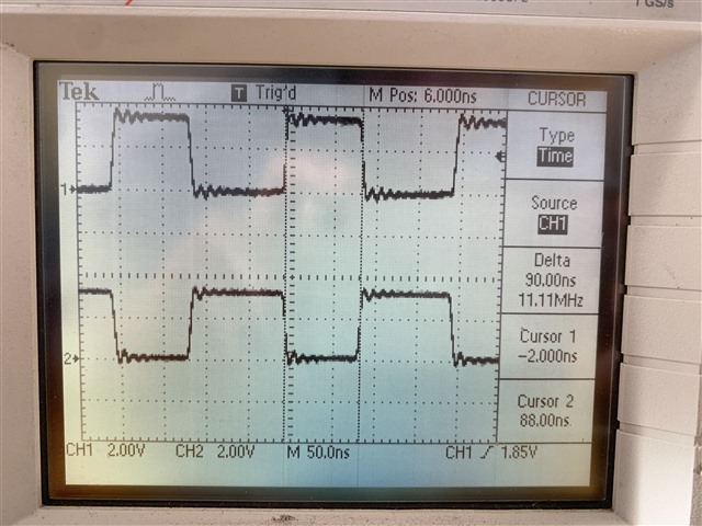
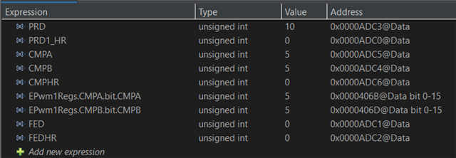
Ex : 200ns -> PRD= 10 and CMP = 5 = 10/2 (same with 240ns etc). I observe a decagle of +/- 1 TBCLK (10ns) for the duty cycle. But the curious thing is that when I modify the value of the period in real time at any period (ex. 208ns) and I change again to 200ns, the duty cycle is 50% and the +/- 1 TBCLK is no longer present. But when I look at the PRD, CMPA, CMPB and CMPHR values in real time they are the same value for the first 200ns period and the 3rd period value (200ns) (screenshots 1 and 3) but we observed a +/-1 TBCLK.
I don't see where this error comes from. And this error is present only if the first period value is equal to 200ns, 240ns or other period with CMP=PRD/2 exactly. But not for other period values (ex 208ns, 220ns etc).
Here are the photos and screenshots different values (PRD, CMPA etc) shot for 200ns then 208ns and back to 200ns with a dynamic value periode:
The code is launched with 200ns (duty cycle set 90ns ) :
 1.
1. 
Je modifie la valeur de periode pour 208 ns (duty cycle : 104 ns) :
 2.
2. 
I set again a period of 200ns (duty cycle : 100ns) :
 3.
3. 
Here's my code if it helps :
#include "F28x_Project.h"
#include "F2837xD_device.h"
#include "F2837xD_Examples.h"
#include "F2837xD_EPwm_defines.h" // init defines
#include "SFO_V8.h"
#include "board.h"
#include <stdio.h>
//--------------- SET PERIOD AND DB ---------------------//
float PeriodeNANOsec = 200; //Periode souhaité en NANOSECONDE
float dutycycle = 0.5;
float dutyDB = 0; //DN(ns)= dutyDB * Periode/2
//-------------- DEFINITION --------------//
#define LAST_EPWM_INDEX 4
//---------------- VARIABLE ----------------//
uint16_t PRD1_HR;
uint16_t FED;
uint16_t FEDHR;
uint16_t PRD;
uint16_t CMPB;
uint16_t CMPA;
uint16_t CMPHR;
//-------------- GLOBAL ------------------------//
int MEP_ScaleFactor;
volatile struct EPWM_REGS *ePWM[] = {0, &EPwm1Regs, &EPwm2Regs, &EPwm3Regs};
uint16_t status;
float DBns;
//---- APPEL DE FONCTION----//
void PRD_CMP_DB_calculation(float32_t periode, float32_t duty,float32_t dutyDB); //calculation of PRD, CMP and DB values (high resolution)
void initGPIO(void); //GPIO initialization
void initPWM(void); //PWM initialization
//****************** CODE PRINCIPAL***********************//
int main()
{
PRD_CMP_DB_calculation(PeriodeNANOsec,dutycycle,dutyDB);
// Initialize System Control for Control and Analog Subsystems
// Enable Peripheral Clocks
EALLOW;
InitSysCtrl();
EDIS;
// EPWM1A and EPWM1B through all PWMS
initGPIO();
DINT;
InitPieCtrl();
// Disable CPU interrupts and clear all CPU interrupt flags:
EALLOW;
IER = 0x0000;
IFR = 0x0000;
InitPieVectTable();
// Enable global Interrupts and higher priority real-time debug events:
EINT; // Enable Global interrupt INTM
ERTM; // Enable Global realtime interrupt DBGM
// Calling SFO() updates the HRMSTEP register with calibrated MEP_ScaleFactor.
// HRMSTEP must be populated with a scale factor value prior to enabling
// high resolution period control.
while(status == SFO_INCOMPLETE)
{
status = SFO(); // SFO function returns 2 if an error occurs & # of MEP
if(status == SFO_ERROR) // steps/coarse step exceeds maximum of 255.
{
ESTOP0;
}
}
SysCtl_disablePeripheral(SYSCTL_PERIPH_CLK_TBCLKSYNC);
initPWM();
SysCtl_enablePeripheral(SYSCTL_PERIPH_CLK_TBCLKSYNC);
uint32_t i;
while(1)
{
float periode; //NEW value of period
printf("New value for the period (in ns): ");
scanf("%f", &periode);
printf("\n");
PRD_CMP_DB_calculation(periode,dutycycle,dutyDB);
for(i=1; i<LAST_EPWM_INDEX; i++)
{
(*ePWM[i]).TBPRD= PRD;
(*ePWM[i]).CMPA.all = (long) CMPA << 16 | CMPHR << 8; //Enable HRPWM duty
(*ePWM[i]).CMPB.all = (long) CMPB << 16 | CMPHR << 8;
(*ePWM[i]).DBRED.all = FED; //Unpacking the assembly
(*ePWM[i]).DBFED.all = FED;
(*ePWM[i]).DBREDHR.bit.DBREDHR = FEDHR; //Unpacking the ascent of the two PW1Ms
(*ePWM[i]).DBFEDHR.bit.DBFEDHR = FEDHR;
(*ePWM[i]).TBPRDHR= PRD1_HR<<8;
}
status = SFO(); // in background, MEP calibration module
// continuously updates MEP_ScaleFactor
if(status == SFO_ERROR)
{
ESTOP0; // SFO function returns 2 if an error occurs & # of
} // MEP steps/coarse step exceeds maximum of 255.
}
}
//------------------ INITIALISATION HRPWM -------------//
void initPWM()
{
uint16_t j;
EALLOW;
CpuSysRegs.PCLKCR0.bit.TBCLKSYNC = 0; // Disable TBCLK within the EPWM
EDIS;
for(j=1; j<LAST_EPWM_INDEX; j++)
{
//------------------ TIME BASE/ CMP --------------------//
(*ePWM[j]).TBCTL.bit.PRDLD = TB_SHADOW; // set Shadow load
(*ePWM[j]).TBPRD= PRD; // PWM frequency = 1/(2*TBPRD))
(*ePWM[j]).CMPA.all = (long) CMPA << 16 | CMPHR << 8; //Enable HRPWM duty
(*ePWM[j]).CMPB.all = (long) CMPB << 16 | CMPHR << 8;
(*ePWM[j]).TBPHS.all = 0;
(*ePWM[j]).TBCTR = 0;
(*ePWM[j]).TBCTL.bit.CTRMODE = TB_COUNT_UPDOWN; // Select up-down count mode
(*ePWM[j]).TBCTL.bit.SYNCOSEL = TB_CTR_ZERO ;
(*ePWM[j]).TBCTL.bit.HSPCLKDIV = TB_DIV1;
(*ePWM[j]).TBCTL.bit.CLKDIV = TB_DIV1; // TBCLK = SYSCLKOUT
(*ePWM[j]).TBCTL.bit.FREE_SOFT = 3;
//-------------------- SHADOWS -------------------------//
(*ePWM[j]).CMPCTL.bit.LOADAMODE = CC_CTR_PRD; // LOAD CMPA on CTR = PRD
(*ePWM[j]).CMPCTL.bit.LOADBMODE = CC_CTR_PRD;
(*ePWM[j]).CMPCTL.bit.SHDWAMODE = CC_SHADOW;
(*ePWM[j]).CMPCTL.bit.SHDWBMODE = CC_SHADOW;
//------------------ ACTION QUALIFIER -------------------//
(*ePWM[j]).AQCTLA.bit.CAU = AQ_SET; // PWM toggle high/low
(*ePWM[j]).AQCTLA.bit.CBD = AQ_CLEAR; //DO NOT SET TO ZRO, HR period is not stable
(*ePWM[j]).AQCTLB.bit.CAU = AQ_CLEAR; // PWM toggle high/low
(*ePWM[j]).AQCTLB.bit.CBD = AQ_SET; //DO NOT SET TO ZRO, HR period is not stable
//--------------------- HRPWM --------------------------//
EALLOW;
(*ePWM[j]).HRCNFG.all = 0x0;
(*ePWM[j]).HRCNFG.bit.EDGMODE = HR_BEP; // BOht Edge for the HR period to work
(*ePWM[j]).HRCNFG.bit.CTLMODE = HR_CMP; // CMPAHR and TBPRDHR HR control.
(*ePWM[j]).HRCNFG.bit.HRLOAD = HR_CTR_ZERO_PRD; // load on CTR = 0 and CTR = TBPRD
(*ePWM[j]).HRCNFG.bit.EDGMODEB = HR_BEP; // BOht Edge for the HR period to work
(*ePWM[j]).HRCNFG.bit.CTLMODEB = HR_CMP; // CMPBHR and TBPRDHR HR control
(*ePWM[j]).HRCNFG.bit.HRLOADB = HR_CTR_ZERO_PRD; // load on CTR = 0 and CTR = TBPRD
(*ePWM[j]).HRCNFG.bit.SWAPAB = 0; // ePWMxA and ePWMxB outputs are unchanged
(*ePWM[j]).HRCNFG.bit.AUTOCONV = 1; // Enable autoconversion for HR period
(*ePWM[j]).HRPCTL.bit.TBPHSHRLOADE = 0; // Enable TBPHSHR sync (required for updwn count HR control)
(*ePWM[j]).HRPCTL.bit.HRPE = 1; // Turn on high-resolution period control.
CpuSysRegs.PCLKCR0.bit.TBCLKSYNC = 1; // Enable TBCLK within the EPWM
(*ePWM[j]).TBCTL.bit.SWFSYNC = 1; // Synchronize high resolution phase to start HR period
//-------------------- DEAD BAND -----------------------//
(*ePWM[j]).DBCTL.bit.IN_MODE = DBA_ALL; //ICI EPWMxA est la source des retards de front descendant et de front montant.
(*ePWM[j]).DBCTL.bit.OUT_MODE= DB_FULL_ENABLE ; // See table 15-8
(*ePWM[j]).DBCTL.bit.POLSEL= DB_ACTV_HIC; //Active High Complementary -> tableau 15-8
(*ePWM[j]).DBCTL.bit.HALFCYCLE= 1; //this bit must be set 1 for HR deadband (clock 5ns for DB)
(*ePWM[j]).DBCTL.bit.OUTSWAP = 0;
(*ePWM[j]).DBCTL.bit.SHDWDBREDMODE = 1;
(*ePWM[j]).DBCTL.bit.SHDWDBFEDMODE = 1;
(*ePWM[j]).DBCTL.bit.LOADREDMODE = 2;
(*ePWM[j]).DBCTL.bit.LOADFEDMODE = 2;
(*ePWM[j]).DBRED.all = FED; //Unpacking the assembly
(*ePWM[j]).DBFED.all = FED;
(*ePWM[j]).HRCNFG2.bit.EDGMODEDB= HR_BEP; // DBREDHR and DBFEDHR
(*ePWM[j]).HRCNFG2.bit.CTLMODEDBFED =2; // Load on ZRO
(*ePWM[j]).HRCNFG2.bit.CTLMODEDBRED =2;
(*ePWM[j]).DBREDHR.bit.DBREDHR = FEDHR; //Unpacking the ascent of the two PW1Ms
(*ePWM[j]).DBFEDHR.bit.DBFEDHR = FEDHR; //Unpacking the descent of the two PW1Ms
(*ePWM[j]).TBPRDHR= PRD1_HR<<8;
EDIS;
}
}
//------------------ INITIALISATION GPIO --------------//
void initGPIO()
{
EALLOW; // Enable access to GPIO configuration registers
// CONFIGURE GPIO 0 FOR PWM1A
GpioCtrlRegs.GPAPUD.bit.GPIO0 = 0; // Activate pull-up resistor on pin
GpioCtrlRegs.GPAMUX1.bit.GPIO0 = 1; // Configure pin for PWM1A function
// CONFIGURE GPIO 1 FOR PWM1B
GpioCtrlRegs.GPAPUD.bit.GPIO1 = 0; // Activate pull-up resistor on pin
GpioCtrlRegs.GPAMUX1.bit.GPIO1 = 1; // Configure pin for PWM1B function
EDIS; // Disable access to GPIO configuration registers
}
void PRD_CMP_DB_calculation(float32_t periode, float32_t duty,float32_t dutyDB)
{
//--------- Period and PRDHR calculation ----------//
float invTBCLK= 0.10; //1/TBCLK = 0.1 nanosec, Number of clock strokes with TBCLK=10ns
float PRDfrac= 0 ;
PRDfrac = periode*invTBCLK*0.5; //Flaot number of TBCLK for the p
PRD=(PRDfrac); //the integer part of the split period
PRD1_HR=((PRDfrac-PRD))*256;
//---------- CMP and CMPHR calculation ------------//
float fracPRD = 0;
fracPRD = periode*invTBCLK;
float reste = 0;
reste = fracPRD * 0.5; //Euclidean division to find out how to calculate CMP at 50%duty
if (reste == (int) reste) //If Periode / (2.TBCLK) is a integer (ex: 180ns / 20 ns = 9 CLK =PRD)
{
float reste2 = 0;
reste2 = PRD *0.5;
if (reste2 == (int) reste2) // if PRD/2 is a integer (ex: 200ns : PRD = 10 CLK and PRD/2 = 5)
{
CMPA=PRD/2;
CMPB = PRD/2 ;
}
else // if PRD/2 is not a integer (ex 180ns -> PRD= 9 CLK and PRD/2= 4.5)
{
float CMPfrac = PRD/2;
CMPA = (CMPfrac);
CMPB = CMPA + 1;
}
}
else //If periode/ 2.TBCLK is not a integer (ex 190ns/20ns = 9.5 CLk =PRD)
{
float CMPfrac = PRD/2;
int CMPent = (CMPfrac);
CMPA = CMPent - 1;
CMPB = CMPent + 1;
}
float frac = 0;
frac = PRDfrac*duty; //calculation of CMPHR = frac(PRDfrc*duty)
int ent = 0;
ent = (frac);
float CMPHRfrac = 0;
CMPHRfrac = frac-ent;
CMPHRfrac = CMPHRfrac*256;
CMPHR=(CMPHRfrac);
//---------- Dead Band and DBHR calculation --------//
float RequiredDBvalue= 0 ;
RequiredDBvalue = duty*periode*dutyDB;
float fracFED= 0 ;
fracFED = RequiredDBvalue*0.2; //*0.2 is equivalent to dividing by 10ns/2 or half a clock cycle
FED=(fracFED);
float fracFEDHR= 0;
fracFEDHR = (fracFED-FED)*128; //DBFED is on 7 bits so for the cacul we realize the (fractionalpart*128)
FEDHR=(fracFEDHR);
}


