This thread has been locked.

If you have a related question, please click the "Ask a related question" button in the top right corner. The newly created question will be automatically linked to this question.

TMS320F28377D-EP: Differential ADC Input driver and Signal conditioning

Part Number: TMS320F28377D-EP
Other Parts Discussed in Thread: OPA320, THS4531

Hi,

I am using hall based current sensor ACS725LLCTR-30AB-T in my design and the supply voltage given to it is 3.3V(Single ended).

The input current is +-24A sinusoidal and the HALL IC is shifting the output to 1.65V, hence the output swing I am getting is 0 to 3.3V(Full current swing) radiometric with supply.

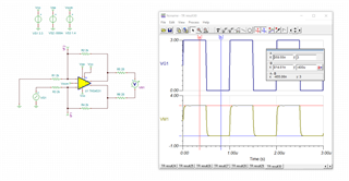
Please find below image for reference circuit.

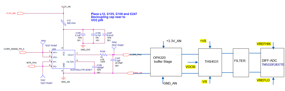
Previously I was using single ended ADC of TMS320F28377DPTPEP, for current sensing so directly given the output of OPA320 buffer stage to the ADC along with filter.

Now I wanted to use a differential 16bit ADC of microcontroller. 

I am planning to use THS4531 diff Amplifier, with the single ended input range 0 to 3V. 

What should be supply voltage given to THS4531 to +VS and -VS pin, and also the VOCM pin highlighted in yellow.

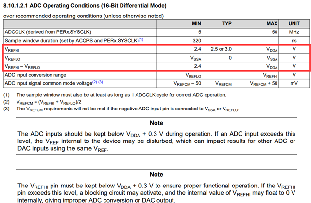
The VREFHI=3V and VREFLO=0V in current design, do we need to change that to VREFHI=1.5V ?

Please provide your inputs so that I could get an idea for starting the design.

Thanks,

Namita

  • Hello Namita,

    I will speak on the questions regarding the F2837xD since that is the part I'm familiar with. The VREFHI and VREFLO for that device must follow the specifications provided by the datasheet for the differential 16-bit ADC configuration:

    The following is the specifications for analog power and ground:

    As long as the VREFHI and VREFLO follow these specifications, the F2837xD differential 16-bit ADC should work within the specified resolution.

    For your other questions on the THS4531, I will forward this question to the proper expert.

  • Hi Namita,

    Based on the requirement of having an input signal of 0 to 3V, you could run Vs+ at 3.3V to use the same supply as other parts of the signal chain. However, you would need to set Vs- below 0V. I have shown a simulation setting Vs+ at 3.3V and Vs- at -0.5V, as shown below:

    THS4531_E2E.TSC

    For Vocm, the recommendation is to run at midsupply as this will provide the most output swing available.

    Thanks,

    Nick