This thread has been locked.

If you have a related question, please click the "Ask a related question" button in the top right corner. The newly created question will be automatically linked to this question.

LAUNCHXL-F28379D: SPI communication errors

Part Number: LAUNCHXL-F28379D
Other Parts Discussed in Thread: C2000WARE

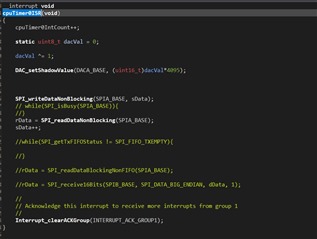
Hi, I'm trying to establish a SPI communication between two 28379D Launchpads. I have configured one as a Master and one as slave. When I execute both of them, I see that the received data in the Master launchpad is very random, it sometimes shows the value from the slave, sometimes directly the sent data on the MOSI line. I'm trying to use the CPU timers for executing the SPI write and read as I need them to be executed at a specific time interval. I have attached the code I have for SPI master setup and the write and read commands in the cputimer interrupt. How do I resolve this issue?

void initSPIBMaster(void)
{
    //
    // Must put SPI into reset before configuring it
    //
    SPI_disableModule(SPIB_BASE);

    //
    // SPI configuration. Use a 500kHz SPICLK and 16-bit word size.
    //
    SPI_setConfig(SPIB_BASE, DEVICE_LSPCLK_FREQ, SPI_PROT_POL0PHA0,
                  SPI_MODE_MASTER, 500000, 16);
    SPI_disableLoopback(SPIB_BASE);
    SPI_setEmulationMode(SPIB_BASE, SPI_EMULATION_FREE_RUN);

    //
    // FIFO and interrupt configuration
    //
    SPI_disableFIFO(SPIB_BASE);
    //SPI_clearInterruptStatus(SPIB_BASE, SPI_INT_TXFF);
    //SPI_setFIFOInterruptLevel(SPIB_BASE, SPI_FIFO_TX2, SPI_FIFO_RX2);
    //SPI_enableInterrupt(SPIB_BASE, SPI_INT_TXFF);

    //
    // Configuration complete. Enable the module.
    //
    SPI_enableModule(SPIB_BASE);
}


__interrupt void
cpuTimer0ISR(void)
{
    cpuTimer0IntCount++;

    static uint8_t dacVal = 0;

    dacVal ^= 1;

    DAC_setShadowValue(DACA_BASE, (uint16_t)dacVal*4095);


    SPI_writeDataBlockingFIFO(SPIB_BASE, sData);

    while(SPI_isBusy(SPIB_BASE)){
    }

    rData = SPI_readDataNonBlocking(SPIB_BASE);

    //
    // Acknowledge this interrupt to receive more interrupts from group 1
    //
    Interrupt_clearACKGroup(INTERRUPT_ACK_GROUP1);
}

Also, if I need to just receive data from slave as SPI Master, which function do I need to use. I'm using device drivers library provided by TI. 

We are trying to setup a BMS Master using this launch pad, so would need to be able to send a register address and then receive information of number of cell voltages and temperatures. Suggest steps that would take us close to achieve this.

Thank you in advance for any response and feel free to revert with any questions for more information.

  • Hi Gauth, 

    Thanks for the information and code. The first thing that stands out to me is are trying to operate in FIFO mode or non-FIFO mode? I see you are disabling FIFOs in your SPI init, but you are using a write-FIFO function and the SPI_isBusy() function which can only be used in FIFO mode. If you are not using FIFO mode, you should adjust to only use functions that are compatible with non-FIFO mode. 

    Some follow up questions as well: Have you looked at any of our C2000Ware examples for reference? Also what is the frequency of your CPUTimer and have you scoped out all four SPI lines to make sure you are seeing expected behavior on them? 

    Best Regards,

    Allison

  • Hi Allison, 

    Thank you for the response, we were trying to resolve the issue by trying out if disabling FIFO would solve anything. We did already try with FIFO enabled and used both read and write functions as BlockingFIFO. In that case too, the same result where the transmit from Master is happening as it should but the readData is not. It just sometimes reads the data from the slave and other times just has the same data as transmit. The behaviour is not as expected on the scope because the STE pin only goes low on SPIwrite command, it goes back high and the MISO line gets interrupted. So receiving data from slave is not happening. 

  • Hi Gauth,

    Thanks for the update. Can you please share the oscilloscope screen shots so I can see? I would also recommend you please reference the C2000Ware example spi_ex3_external_loopback_fifo_interrupts.c located at {C2000Ware}\driverlib\f2837xd\examples\cpu1\spi. I think this would be really helpful for what you are trying to accomplish here. Let me know if you are able to implement some of the same settings/use a similar code format for this.

    Also, can you please share what the CPUTimer frequency is?

    A few other notes to make sure we align on understanding how the SPI module works:

    • Any time you transmit a byte of data from the master by writing to the transmit buffer, the master device will ALSO receive a byte of data simultaneously and store it in the receive buffer
    • The chip select (SPISTE pin) will go low while the master is writing. Once the transmission from master to slave is complete, it should go back to inactive/high. This is because transmission and receival of data occurs simultaneously. I'd still like to see your scope shots though to view what is happening in your case.

    Best Regards,

    Allison

  • Hi Allison,

    I did use spi_ex3_external_loopback_fifo_interrupts.c as an example to start with. But that only has the Master (SPIB) transmitting data and the Slave (SPIA) receiving. I have taken the config definitions for the SPI from that example and tried to implement in a new project with cputimers instead of having interrupts (timer_ex1_cputimers as base).

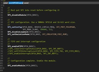
    We are running the same cputimers on both the master and the slave. The below is the code for Slave

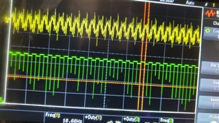
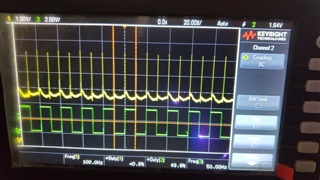
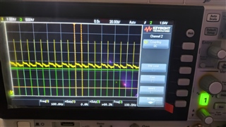
    The below are the scope shots. Note that in all the images, yellow is the clock pin. The cputimer0 is executing at 100Hz. 

    SOMI and CLK

    SIMO and CLK

    STE and CLK

    Please have a look and let me know any further questions for getting a clear picture of the issue here. 

    Thanks

    Gautham 

  • Hi Gautham,

    Glad you were able to take a look at the example before.

    The scope shots you attached are a bit confusing to me - is each pulse seen on the screen corresponding to a single CPUTimer interrupt happening? This is what I speculate, meaning you are zoomed out too much to see what is happening in each ISR. You would need to zoom in to see individual clock pulses and the chip select going low for a duration rather than a short spike. (Please correct me if my interpretation is wrong)

    I don't see any issues with initiating the transmission by writing to SPITXBUF in the CPUTimer ISR. However, when you are reading, you should be checking that there is valid data in the receive FIFO before trying to read data from there. Or, instead of a while loop in the CPUTimer ISR, you could use a SPI interrupt at a particular receive FIFO level to let you know that you received data. Then you can read the data from SPIRXBUF in the SPIRXINT ISR and just use the CPUTimer ISR to initiate the transfer at a specified time.

    This is because when you transmit data, you are also receiving data into the RX FIFO simultaneously, but if you try to read from the receive buffer immediately after writing to transmit buffer, you could be reading incomplete data. You should check that the RXFFST (receive FIFO status) shows there is at least the expected number of words present in the RX FIFO ready to be read. 

    Best Regards,

    Allison

  • Hi Allison,

    You are right when you say that the scope images are way zoomed out.

    I have tried using the RxFF Interrupt for reading the data, the code for that is attached below. I enabled the Rx interrupt and executed the readData function in the ISR and yet, the same result. In this case, we used a constant value sent from the slave device but the data read in the master is not constant but varying between the data in transmit buffer and I have also observed that sometimes it misses reads a left shifted data (it read 127 when sent 255).


    __interrupt void spibRxFIFOISR(void)
    {
    
       //
       // Read data
       //
    
       rData = SPI_readDataNonBlocking(SPIB_BASE);
    
       rDataPoint++;
    
       //
       // Clear interrupt flag and issue ACK
       //
       SPI_clearInterruptStatus(SPIB_BASE, SPI_INT_RXFF);
       Interrupt_clearACKGroup(INTERRUPT_ACK_GROUP6);
    
       Example_PassCount++;
    }
    void initSPIBMaster(void)
    {
        //
        // Must put SPI into reset before configuring it
        //
        SPI_disableModule(SPIB_BASE);
    
        //
        // SPI configuration. Use a 500kHz SPICLK and 16-bit word size.
        //
        SPI_setConfig(SPIB_BASE, DEVICE_LSPCLK_FREQ, SPI_PROT_POL0PHA0,
                      SPI_MODE_MASTER, 500000, 16);
        SPI_disableLoopback(SPIB_BASE);
        SPI_setEmulationMode(SPIB_BASE, SPI_EMULATION_FREE_RUN);
    
        //
        // FIFO and interrupt configuration
        //
        SPI_enableFIFO(SPIB_BASE);
        SPI_clearInterruptStatus(SPIB_BASE, SPI_INT_RXFF);
        SPI_setFIFOInterruptLevel(SPIB_BASE, SPI_FIFO_TX2, SPI_FIFO_RX2);
        SPI_enableInterrupt(SPIB_BASE, SPI_INT_RXFF);
    
        //
        // Configuration complete. Enable the module.
        //
        SPI_enableModule(SPIB_BASE);
    }

    Please have a look and inform if I'm missing anything here.

    Thanks

    Gautham

  • Hi Gautham,

    Can you send scope shots that are zoomed in so we can check that the communication lines look ok? (i.e. chip select goes low, SPI clock looks normal, data is being sent properly). This is the easiest way to determine there are no obvious issues with communication. Also, the video you attached appears to cut off what the expression names are - looks like they are interrupt counts though. Could you explain a bit of context as to what is occurring in the video (sorry it's a bit blurry for me)?

    I wanted to ask how much data and what size of data you are expecting to be stored in rdata (16-bit data, correct?). And can you also send the latest updated CPUTimer ISR code and SPI slave setup?

    Best Regards,

    Allison

  • Hi Allison,

    The following function has resolved the issues I was facing. Now, I'm able to use this directly within the CPUTimer ISR instead of SPI_INT_RXFF.

    SPI_pollingFIFOTransaction(uint32_t base, uint16_t charLength,
    uint16_t *pTxBuffer, uint16_t *pRxBuffer,
    uint16_t numOfWords, uint16_t txDelay);

    Could you may be let me know the difference between this and the SPI_read and SPI_write functions that I was trying to use before?

  • Hi Gautham,

    Glad you were able to resolve the issue and use CPUTimer! 

    The SPI_writeDataBlockingFIFO() and SPI_readDataBlockingFIFO() functions only write and read one character of data to/from the FIFOs. Contrastingly, the SPI_pollingFIFOTransaction() function writes and reads all the specified number ('N') of characters all at once (it actually uses the SPI_write and SPI_read functions above, but does back-to-back transmissions and reads). It also resets the FIFOs to default state and redefine's the character length, which is not done in the simpler write/read functions, and can add delay between data transmissions if specified. Let me know if you have further questions here or issues.

    Best Regards,

    Allison