This thread has been locked.

If you have a related question, please click the "Ask a related question" button in the top right corner. The newly created question will be automatically linked to this question.

TMS320F28377D: Sampling issues with chips

Part Number: TMS320F28377D

The sampling issues encountered during the use of TMS320F28377DZWTS are as follows:

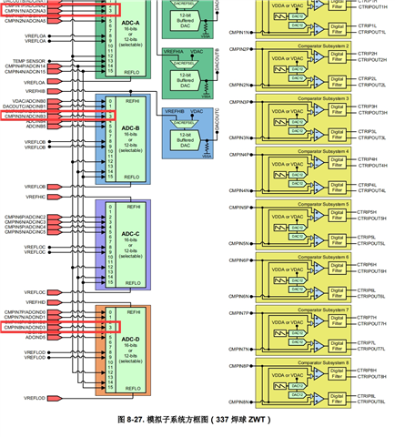
This chip is applied in the 100kw PCS energy storage project, with 4 sets of - ADC (ADCA~ADCD) sampling configurations used to sample the voltage and current of the PCS system. Currently, it is configured as a single ended 12 bit - ADC mode, with an ADC reference power supply of 3V. The problem is that the data collected from the ADCD channel fluctuates more than the data collected from other channels, as shown in the following figure:

Based on the data, there are several suspicious directions: 1) ADC reference power supply, 2) PCB layout, and 3) software configuration application. We have conducted the following verification tests on our end:

--PCB wiring, sampling and conditioning circuit filtering parameter verification:

1) The ADC port of the chip exchanges data between ADCA3 and ADCD3, but there are still significant fluctuations in the ADCD3 channel data.

2) ADCA3, ADCB3, and ADCD3 all collect data from the input of the ADCA3 channel, but the ADCD3 channel data fluctuates greatly.

3) ADCA3, ADCB3, and ADCD3 all collect data from the input of the ADCD3 channel, but the ADCD3 channel data fluctuates greatly.

4) Increasing the filtering degree of ADCD3 channel conditioning parameters is ineffective, but the ADCD3 channel still fluctuates greatly.

--Power supply verification:

5) Using an external power supply to provide ADC front-end operational amplifier conditioning circuit power and a 3V reference power supply to read data, there are still significant fluctuations in ADCD3 channel data.

6) Adding a 3V reference power input decoupling capacitor has no effect, but there is still significant fluctuation in the ADCD3 channel.

--Software configuration verification:

7) Adjusting the sampling and holding time of the ADC converter/adjusting the conversion order of various channels inside the ADCD showed no signs of improvement, but there were still significant fluctuations in the ADCD3 channel data.

Please assist in reviewing this issue, thank you!

  • Hello,

    Apologies for the delayed response, there was a holiday in the US yesterday.

    To clarify some of the items you verified, did you check whether the analog signal supplied to ADC D3 was itself a clean signal? If you connect the same analog signal to another ADC input, is the reading the same as you saw with D3?

    Are there any electrical signals near D3 which may oscillate frequently or produce ESD?

    2) ADCA3, ADCB3, and ADCD3 all collect data from the input of the ADCA3 channel, but the ADCD3 channel data fluctuates greatly.

    3) ADCA3, ADCB3, and ADCD3 all collect data from the input of the ADCD3 channel, but the ADCD3 channel data fluctuates greatly.

    Can you clarify what you mean by A3, B3, and D3 collect data from A3/D3?

  • 1) Question 1: Is the analog signal of ADC D3 itself a clean signal If you connect the same analog signal to another ADC input, does the reading match what you see on D3?

    1) Answer 1: It is a clean signal. We send the same signal to two different ADC inputs (such as ADCA3 and ADCD3 channels), and the result is that ADCD3 fluctuates while ADCA3 does not.

    2) Question 2:Is there any electrical signal near D3 that may frequently oscillate or generate ESD?

    2) Answer 2: There is no high-frequency digital signal near D3.

    3) Answer 3: ADCA3/ADCD3 is a 28377d ADC sampling input channel, as shown below:

  • Hello,

    To reiterate:

    • The input the ADC D3 is exactly the same as the input to ADC A3/B3
    • The hardware of the A3/B3/D3 connections is the same
    • Increasing the ACQPS did not improve the signal read by ADC D3
    • There are no sources of high frequency noise near/around the ADC D3 input
    • Besides the pin number, A3/B3/D3 are configured exactly the same in software
      • The chosen VREFs are the same
    • Voltages within the F2837xD's datasheet tolerances are used (nothing below minimum or above maximum)

    I will discuss this with some other experts to see if there are any routing concerns internal to the device. I will get back to you once I get a reply from them.

  • Can you also provide how you're triggering the ADCs? If you're trying to use them synchronously, then they must have the same trigger source. You can review more information about using synchronous sampling by looking at section 11.13.1 Ensuring Synchronous Operation in the ADC chapter of the reference manual.