Other Parts Discussed in Thread: UCC2895
I wanted to realize Cycle by cycle trip using CMPSS and epwm module. where the CMPIN1P is fed externally and compared with a DAC value to generate the trip signal. I referred the example code for CMPSS given as One shot trip and modified it to work for Cycle by cycle.
For One shot trip code
I used a fixed DC value for CMPIN1P and when trip signal is generated the one shot trip is forcing the pwm pulses to go high.
and when There is no trip signal the PWM are normal as expected.
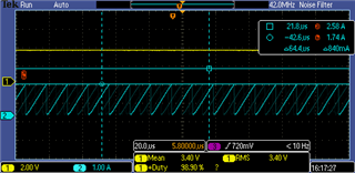
For Cycle by Cycle Trip
here also when used fixed DC value for CMPIN1P trip generated and the pwm pulses go high instead of cycle by cycle trip.
Am i missing out on some configuration here?
the code is as follows:
void initEPWM(void)
{
EPwm8Regs.TBCTL.bit.HSPCLKDIV = TB_DIV1; // Clock ratio to SYSCLKOUT
EPwm8Regs.TBCTL.bit.CLKDIV = TB_DIV1;
EPwm8Regs.TBCTL.bit.PRDLD = TB_SHADOW;
EPwm8Regs.TBCTL.bit.PHSEN = TB_DISABLE; // Enable phase loading
EPwm8Regs.TBCTL.bit.SYNCOSEL = TB_CTR_ZERO; // Disable Phase sync
EPwm8Regs.TBCTL.bit.CTRMODE = TB_COUNT_UP; // Count up/down mode
EPwm8Regs.TBPHS.bit.TBPHS = 0x0000; // Phase is 120
EPwm8Regs.TBCTR = 0x0000;
//switching frequency = 80kHz
EPwm8Regs.TBPRD = 1250; // Set UCC2895 clock
// Setup shadow register load on ZERO
EPwm8Regs.CMPCTL.bit.SHDWBMODE = CC_SHADOW ;
EPwm8Regs.CMPCTL.bit.LOADBMODE = CC_CTR_ZERO;
// 1.667us Clock pulse width
EPwm8Regs.CMPB.bit.CMPB = 300;
// Active low configuration
EPwm8Regs.AQCTLB.bit.CBU = AQ_SET;
EPwm8Regs.AQCTLB.bit.ZRO = AQ_CLEAR;
//
//Configure EPWM8B to output high on TZB TRIP
//
EPwm8Regs.TZCTL.bit.TZB = TZ_FORCE_HI;
EPwm8Regs.TZSEL.bit.DCBEVT2 = 1;
EPwm8Regs.TZCLR.bit.CBCPULSE = 0;
EPwm8Regs.TZDCSEL.bit.DCBEVT2 = TZ_DCBH_HI;
EPwm8Regs.DCTRIPSEL.bit.DCBHCOMPSEL = 0xF;
EPwm8Regs.DCBHTRIPSEL.bit.TRIPINPUT4 = 1;
//Configure DCB path to be unfiltered & async
EPwm8Regs.DCBCTL.bit.EVT2SRCSEL = DC_EVT2;
EPwm8Regs.DCBCTL.bit.EVT2FRCSYNCSEL = DC_EVT_ASYNC;
//Configure TRIP4 to be CTRIP1H
EPwmXbarRegs.TRIP4MUX0TO15CFG.bit.MUX0 = 0;
//Enable TRIP4 Mux for Output
EPwmXbarRegs.TRIP4MUXENABLE.bit.MUX0 = 1;
// Clear trip flags
EPwm8Regs.TZCLR.bit.CBC = 1;
EPwm8Regs.TZCLR.bit.INT = 1;
EPwm8Regs.TZCBCCLR.bit.DCBEVT2 = 1;
EPwm8Regs.TZEINT.bit.CBC = 1;
void initCMPSS(void)
{
//
// Enable CMPSS and configure the negative input signal to come from
// the DAC
//
CMPSS_enableModule(CMPSS1_BASE);
CMPSS_configHighComparator(CMPSS1_BASE, CMPSS_INSRC_DAC);
//
// Use VDDA as the reference for the DAC and set DAC value to midpoint for
// arbitrary reference.
//
CMPSS_configDAC(CMPSS1_BASE, CMPSS_DACREF_VDDA | CMPSS_DACVAL_SYSCLK |
CMPSS_DACSRC_SHDW);
CMPSS_setDACValueHigh(CMPSS1_BASE, 500);
//
// Configure the output signals. Both CTRIPH and CTRIPOUTH will be fed by
// the asynchronous comparator output.
//
CMPSS_configOutputsHigh(CMPSS1_BASE, CMPSS_TRIP_ASYNC_COMP |
CMPSS_TRIPOUT_ASYNC_COMP);
//
// Setup the Output X-BAR to output CTRIPOUTH on OUTPUTXBAR3
//
XBAR_setOutputMuxConfig(XBAR_OUTPUT3, XBAR_OUT_MUX00_CMPSS1_CTRIPOUTH);
XBAR_enableOutputMux(XBAR_OUTPUT3, XBAR_MUX00);
}