This thread has been locked.

If you have a related question, please click the "Ask a related question" button in the top right corner. The newly created question will be automatically linked to this question.

TMS320F28386D: Internal Oscillator configuration not working for TMS320f28386D

Part Number: TMS320F28386D
Other Parts Discussed in Thread: SYSCONFIG, TMS320F28388D, C2000WARE, UNIFLASH

Hello,

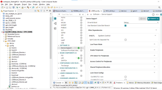
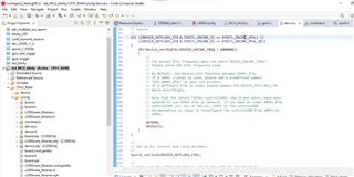
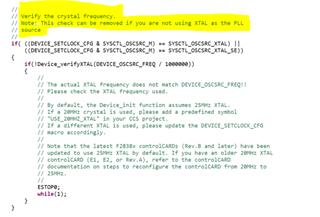
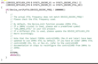
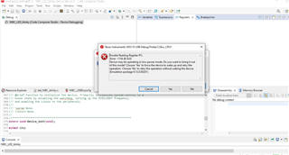
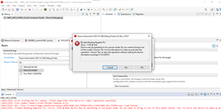
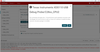
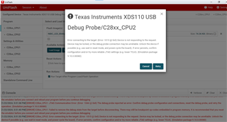
I am using the evolution board(TMS320F28386D) having the External oscillator and while debugging i didn't face any issue. But whenever i switch the board from TMS320F28388D  to TMS320F28386D with internal oscillator by SYSCONFIG Tool, my code get hanged at Device_init(), Kindle let me know how to solve the issue. 

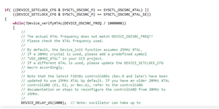
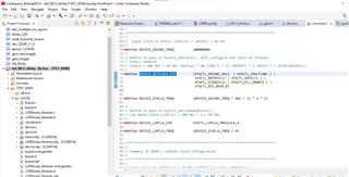
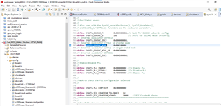
When i tried to debug using TMS320F28386D which is having the internal oscillator, code is getting hanged at while () and Device_delay() functions. please let me know why it is hanging there and share the comments

Regards

Bandi

  • Hi Bandi,

    Have you enabled the device_support option in the sysconfig tool for the clocktree changes to get reflected?

    Also can you share the clocktree.h file generated by sysconfig ?

    Can you share the DEVICE_SETCLOCK_CFG macro configuration in the device_init funciton, to confirm whether the program is correctly pointing to the clocktree.h for the macro defiinition.

    //
    // Set up PLL control and clock dividers
    //
    SysCtl_setClock(DEVICE_SETCLOCK_CFG);

    Thanks

    Aswin

  • Hello Aswin,

    I am sharing the screen shot related to device support in sysconfig, Please guide me how can i enable the device_support option in the sysconfig tool for the clocktree changes to get reflected.

    And also sharing the clocktree.h file generated for internal oscillator for TMS320F28386D

    //#############################################################################
    //
    // FILE:   clockTree.h
    //
    // TITLE:  Setups device clocking for examples.
    //
    //#############################################################################
    // $Copyright:
    // Copyright (C) 2024 Texas Instruments Incorporated - http://www.ti.com
    //
    // Redistribution and use in source and binary forms, with or without 
    // modification, are permitted provided that the following conditions 
    // are met:
    // 
    //   Redistributions of source code must retain the above copyright 
    //   notice, this list of conditions and the following disclaimer.
    // 
    //   Redistributions in binary form must reproduce the above copyright
    //   notice, this list of conditions and the following disclaimer in the 
    //   documentation and/or other materials provided with the   
    //   distribution.
    // 
    //   Neither the name of Texas Instruments Incorporated nor the names of
    //   its contributors may be used to endorse or promote products derived
    //   from this software without specific prior written permission.
    // 
    // THIS SOFTWARE IS PROVIDED BY THE COPYRIGHT HOLDERS AND CONTRIBUTORS 
    // "AS IS" AND ANY EXPRESS OR IMPLIED WARRANTIES, INCLUDING, BUT NOT 
    // LIMITED TO, THE IMPLIED WARRANTIES OF MERCHANTABILITY AND FITNESS FOR
    // A PARTICULAR PURPOSE ARE DISCLAIMED. IN NO EVENT SHALL THE COPYRIGHT 
    // OWNER OR CONTRIBUTORS BE LIABLE FOR ANY DIRECT, INDIRECT, INCIDENTAL, 
    // SPECIAL, EXEMPLARY, OR CONSEQUENTIAL DAMAGES (INCLUDING, BUT NOT 
    // LIMITED TO, PROCUREMENT OF SUBSTITUTE GOODS OR SERVICES; LOSS OF USE,
    // DATA, OR PROFITS; OR BUSINESS INTERRUPTION) HOWEVER CAUSED AND ON ANY
    // THEORY OF LIABILITY, WHETHER IN CONTRACT, STRICT LIABILITY, OR TORT 
    // (INCLUDING NEGLIGENCE OR OTHERWISE) ARISING IN ANY WAY OUT OF THE USE 
    // OF THIS SOFTWARE, EVEN IF ADVISED OF THE POSSIBILITY OF SUCH DAMAGE.
    // $
    //###########################################################################
    
    #ifndef CLOCKTREE_H
    #define CLOCKTREE_H
    
    //*****************************************************************************
    //
    // Summary of SYSPLL related clock configuration
    //
    //*****************************************************************************
    //
    // Input Clock to SYSPLL (OSCCLK)	= 10 MHz    (INTOSC1 provides OSCCLK)
    //
    //##### SYSPLL ENABLED #####
    //
    // PLLRAWCLK				= 200 MHz   (Output of SYSPLL if enabled) 
    // PLLSYSCLK				= 200 MHz
    // CPU1CLK					= 200 MHz
    // CPU2CLK					= 200 MHz 
    // CPU1_SYSCLK				= 200 MHz
    // CPU2_SYSCLK 				= 200 MHz
    // LSPCLK					= 50 MHz 
    	
    //*****************************************************************************
    //
    // Macro definitions used in device.c (SYSPLL / LSPCLK)
    //
    //*****************************************************************************
    //
    //	Input Clock to SYSPLL (OSCCLK) = INTOSC1 = 10 MHz
    //
    #define DEVICE_OSCSRC_FREQ          10000000U
    //
    // Define to pass to SysCtl_setClock(). Will configure the clock as follows:
    // SYSPLL ENABLED
    // SYSCLK = 200 MHz = 10 MHz (OSCCLK) * 40 (IMULT) / (1 (REFDIV) * 2 (ODIV) * 1 (SYSCLKDIVSEL))
    //
    #define DEVICE_SETCLOCK_CFG         (SYSCTL_OSCSRC_OSC1  | SYSCTL_IMULT(40) | \
    									 SYSCTL_REFDIV(1) | SYSCTL_ODIV(2) | \
    									 SYSCTL_SYSDIV(1) | SYSCTL_PLL_ENABLE | \ 
    									 SYSCTL_DCC_BASE_0)
    									 
    									 
    #define DEVICE_SYSCLK_FREQ          (DEVICE_OSCSRC_FREQ * 40) / (1 * 2 * 1)
    
    //
    // Define to pass to SysCtl_setLowSpeedClock().
    // Low Speed Clock (LSPCLK) = 200 MHz / 4 = 50 MHz
    //
    #define DEVICE_LSPCLK_CFG  			SYSCTL_LSPCLK_PRESCALE_4
    
    #define DEVICE_LSPCLK_FREQ          (DEVICE_SYSCLK_FREQ / 4)
    
    
    //*****************************************************************************
    //
    // Summary of AUXPLL related clock configuration
    //
    //*****************************************************************************
    //
    // Input Clock to AUXOSCCLK	= 10 MHz (INTOSC2 provides AUXOSCCLK)  
    //
    //##### AUXPLL ENABLED #####
    //
    // AUXPLLRAWCLK				= 100 MHz (Output of AUXPLL if enabled)
    // AUXPLLCLK				= 100 MHz 
    //
    //*****************************************************************************
    //
    // Macro definitions used in device.c (AUXPLL)
    //
    //*****************************************************************************
    //
    //	Input Clock to AUXPLL (AUXOSCCLK) = INTOSC2 = 10 MHz
    //
    #define DEVICE_AUXOSCSRC_FREQ 		10000000U
    //
    // Define to pass to SysCtl_setAuxClock(). Will configure the clock as follows:
    // AUXPLL ENABLED
    // AUXPLLCLK = 100 MHz = 10 MHz (AUXOSCCLK) * 40 (IMULT) / (1 (REFDIV) * 4 (ODIV) * 1 (AUXCLKDIVSEL))
    #define DEVICE_AUXCLK_FREQ          (DEVICE_OSCSRC_FREQ * 40) / (1 * 4 * 1)
    //
    #define DEVICE_AUXSETCLOCK_CFG      (SYSCTL_AUXPLL_OSCSRC_OSC2  | SYSCTL_AUXPLL_IMULT(40) | \
    									 SYSCTL_REFDIV(1) | SYSCTL_ODIV(4)| \
    									 SYSCTL_AUXPLL_DIV_1 | SYSCTL_AUXPLL_ENABLE | \
    									 SYSCTL_DCC_BASE_0)


    //*****************************************************************************
    //
    // CPU1CLK / CPU2CLK Domain (200 MHz)
    //
    //*****************************************************************************
    // VCU
    // TMU
    // FPU
    // Flash
    // DCSM
    // HWBIST
    //	
    
    //*****************************************************************************
    //
    // CPU1 SYSCLK Domain (200 MHz)
    //
    //*****************************************************************************
    // CPUTIMERx
    // DMA
    // CLA1
    // XINT
    // PIE
    // LSxRAMs
    // MSGRAMs
    // Mx/DxRAM
    // BootROM
    // BGCRC
    // ERAD
    // EMIF2
    // WDCLK
    //	
    
    /////////////////////	
    // Gated CPU1 SYSCLK
    /////////////////////
    // USB
    //
    
    //*****************************************************************************
    //
    // CPU2 SYSCLK Domain (200 MHz)
    //
    //*****************************************************************************
    // CPUTIMERx
    // DMA
    // CLA1
    // XINT
    // PIE
    // LSxRAMs
    // MSGRAMs
    // Mx/DxRAM
    // BootROM
    // BGCRC
    // ERAD
    //
    	
    /////////////////////	
    // Gated CPU2 SYSCLK
    /////////////////////
    // CPU2_CLA1
    // CPU2_DMA
    // CPU2_Timer
    //
    //*****************************************************************************
    //
    // Gated Peripheral EPWM Domain ( MHz) 
    //
    //*****************************************************************************
    // EPWM
    // HRPWM
    //
    //*****************************************************************************
    //
    // Gated Peripheral SYSCLK Domain (200 MHz) 
    //
    //*****************************************************************************
    // ADC
    // CMPSS
    // DAC
    // ePWM
    // HRPWM
    // eCAP
    // eQEP
    // I2C
    // McBSP
    // SDFM
    // FSI
    // PMBUS
    // HRCAL
    // SPI
    // SCI
    // DCC
    // CAN
    //	
    //*****************************************************************************
    //
    // Gated LSPCLK Domain (50 MHz) 
    //
    //*****************************************************************************
    // SCI
    // SPI
    // McBSP
    
    #endif // CLOCKTREE_H


    And also sharing the DEVICE_SETCLOCK_CFG macro configuration in the device_init funciton, to confirm whether the program is correctly pointing to the clocktree.h for the macro definition and also SysCtl_setClock(DEVICE_SETCLOCK_CFG);

    If i click on the DEVICE_SETCLOCK_CFG it is displaying the clocktree.h content only

    Finally sharing the  DEVICE_SETCLOCK_CFG macro configuration in the device_init funciton                                                     

    Please refer and let me know for ant modifications required

    Regards

    Bandi

  • Hi Bandi,

    If you are using INTOSC, then you can remove this check. It is mentioned as a note just above the if condition.

    Thanks

    Aswin

  • Hello Aswin,

    Could you please help me how to the device_support option in the sysconfig tool for the clocktree changes to get reflected.

    And also if i remove the code related to XTAL then do i write and  add any function related to INTOSC1, as i am using the internal oscillator for TMS320F28386D (Custom Board).

    I removed the below attached code, should i add any function to use internal oscillator?

    Thanks & Regards

    Bandi 

  • Hi Bandi,

    Could you please help me how to the device_support option in the sysconfig tool for the clocktree changes to get reflected.

    You have made the correct enablement of the device_support option in the syscfg.

    What i meant was if you are using the existing C2000ware examples without clocktree configuration, it would have default device.h/.c files which has the clock configurations.

    If you are using clocktree to configure the clock, you just need to add device_support in sysconfig( which you have done) and exclude the existing (if any) device.h/.c while building the example

    And also if i remove the code related to XTAL then do i write and  add any function related to INTOSC1, as i am using the internal oscillator for TMS320F28386D (Custom Board).

    No you don't need to add any additional function to use INTOSC as the source.

    Thanks

    Aswin

  • Hi Aswin,

                   After all the above changes i am getting an error

    Any suggestion what might causing this issue, i have been struggling this issue for 2 weeks. Can you please guide me how to resolve this

    Thanks & regards

    Bandi

  • Hi Bandi,

    Have you tried restarting the board (power off and on) and tried again?

    Did you make any configuration to run in low power mode?

    Try creating a separate workspace, new target configuration and try again (Just to confirm if the workspace/target config has no issues)

    Also do you face this issue while loading the program or is it while reading some register value?  And did you face it in all the devices available with you ?

    Thanks

    Aswin

  • Hello Aswin,

    I tried restarting the board (power off and on) and tried again and again, also created a new project using new workspace still i am facing the error while loading the program

    I tried with the UNIFLASH tool there also getting the same error

    When i tried for multiple power off/ on and reset the power for board in between i am getting below error

    Can you please help to come out of this issue

    Thank & Regards

    Bandi

  • Hi Bandi,

    Are you able to connect your device? Is the issue coming when you are trying to load the program?

    If you are able to connect to the device, i suggest you to erase the flash and try again loading.

    Connect the target -> go to tools -> click On_chip flash  ->  go to erase flash option in the on-chip flash view

    Thanks

    Aswin

  • Hello Aswin,

    Still I am unable to connect the device, I am facing below while loading the program

    I tried to erase the flash using On_chip flash under TOOL, but unable to find the  On_chip flash option 

    I tried using UNIFLASH tool also getting the same issue

    Could you please suggest us why the device is behaving like this?

    we were using TMS320F28386D device with custom board, it's been 3 weeks we were trying to flash the code into the target

    Regards

    Bandi

  • Hi Bandi,

    I am assuming you have loaded some code in the FLASH configuration to have the device go into low power mode.

    So everytime you try to connect the device, it will have this issue.

    Please confirm if the board is powered properly.

    I suggest you to update the boot configuration from BOOT from flash to other option in the emulation board. Look for the S1-A switch on the hardware.

    S1:A - Emulation & GPIO28 Switch

    POS 1 ON: Use xds100v2 emulator that is on the cCARD

    POS 1 OFF: Boot from FLASH/peripheral (see boot mode switch) OR use emulator on baseboard

    POS 2 ON: GPIO28 will be controlled by the USB-to-UART adapter on the FTDI chip

    POS 2 OFF: GPIO28 can be controlled by a pin in HSEC connector

    Currently the boot pin setting (POS 1) will be OFF, you can make it as ON (so that it doesn't boot from flash)

    Then you should be able to connect to the device and you should be able to see the On-chip flash option in the tools menu. Then follow the steps in the previous reply.

    Let me know if you are able to come out of the issue.

    Thanks

    Aswin

  • Hello Aswin,

    I am glad to say that, now I am able to flash and run the code using RAM (CPU1_RAM) Module, but when i tried device is configured for boot to flash code using FLASH (CPU1_FLASH) getting the below error.

    Could you please help me this?

    Thanks 

    Bandi

  • Hi Bandi,

    Glad that you are able to load in RAM config.

    Have you erased the flash as mentioned in the previous reply using the ON-chip flash option in the tools menu? if not can you do it ?

    I think there is another program still residing in the FLASH, which is causing the issue.

    Can you try to load the program in FLASH config disabling the boot to flash switch in the emulation board?

    Set S1-A -> POS1 - ON and try loading to CPU1_FLASH config and see if you are able to load the program.

    I am not sure if the example that you are using is provided in the C2000Ware SDK, if not can you try loading any existing example in the C2000Ware SDK.

    Thanks

    Aswin

  • Hello Aswin,

    As you said i tried to erase the FLASH  using ON-CHIP on tools, Still facing the below error

    I Set S1-A -> POS1 - ON and try loading to CPU1_FLASH configured, I could able to flash from TMS320F28388D (control card), here also when i TURN OFF power and TURN ON program is not staying forever(LED blink disappeared after reset) but not even loading from Flash_cpu1 (TMS320F28386D) from custom board.

    could you please help me

    Thanks & regards

    Bandi

  • Hi Bandi,

    Since the S1-A POS1 is set in ON position, it will not boot from flash. 

    You need to make the switch to OFF position to make it run in standalone FLASH configuration after you do a TURN OFF and TURN ON.

    I Set S1-A -> POS1 - ON and try loading to CPU1_FLASH configured, I could able to flash from TMS320F28388D (control card),

    So were you able to blink the led in CPU1_FLASH configuration?

    Thanks

    Aswin