


Other Parts Discussed in Thread: TMS320F280049, C2000WARE
Hi everyone, I come across a confusing problem.
Problem description: When using the BIOS app.cfg to select the external oscillator as system clock source, the TMS320F28075 chip sometimes fail to set two ClkCfgRegs registers under the particular power sequence after the control board is powered up. Yet when using the InitSysPll library function, or using the BIOS app.cfg to set INTOSC2 as the system clock, this problem did not happen once in many runs. I changed several control boards, the results is all the same.
Problem Background: A Photovoltaic grid-connected inverter control board contains two DSP, a primary DSP is TMS320F28075, a secondary DSP is TMS320F280049, two chips share the power supply circuit. There are two GPIO pins and several SPI pins connected to each other for the detection of each other's "heartbeat" and the master-slave communication. Both chips use an passive external oscillator as the clock source. TMS320F28075 set system clock by BIOS app.cfg, TMS320F280049 set system clock by a function, because these two projects were finished by different engineers.
My questions:
1. Is there a difference between using BIOS app.cfg to configure the system clock and using InitSysPll library function? Where can I found the evidence(source code of the system clock setting in the boot module of the BIOS app.cfg)?
2.Why would the TMS320F28075 chip failed to set some ClkCfgRegs registers when using the BOIS app.cfg to select the external oscillator as system clock source under the particular power sequence? The power sequence is in the range of the requirement. Is it only a surface representation caused by other things(such as the system clock of the TMS320F280049 chip is normal yet antoher is not, it caused a current or voltage difference), or the reason that caused this problem?
Problem details:
I tried to use the help and find a Boot.c file in C:\ti\bios_6_51_00_15\packages\ti\catalog\c2800\initF2837x


Then I modified the Boot_configurePllDivs function in Boot.c in the same setting logic with the InitSysPll library function. Yet I found it wasn't compiled into the project.
The comparison of the exported ClkCfgRegs whether the TMS320F28075 chip occur this problem is shown as follows(The left side is normal, the right side is abnormal)

The above ClkCfgRegs show that when this problem occurs, the PLL is bypassed and unlocked, the SYSPLL multiplier register failed to set, yet the divider select register succeed, which result in the system frequency is 24 times slower than the expected status.
TMS320F28075 system clock settings in the form of XGCONF is shown as follows
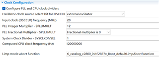
The corresponding cfg script is shown as follows


The simple test code for this problem is shown as follows

When disable the BIOS app.cfg clock settings, every method in the above program is fine. When enable the BIOS app.cfg clock settings, if the problem occurs, every method in the above program will stuck at the while loop in the InitSysPll which wait for the SYSPLL is locked. If the problem doesn’t occur, every method in the above program is fine. This means the system clock cannot be set again after the problem occurs.
The comparison of the detected power sequence whether the problem occurs is shown as follows(among all the power-on related pins, choose a VDDIO pin(CH2), a VDDA pin(CH3) of the TMS320F28075 as the measurement object, CH1 is a SPISOMI pin of the TMS320F28075)
The detected power sequence when the ClkCfgRegs is normal

The detected power sequence when the ClkCfgRegs is abnormal
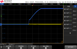
This problem is more likely to occur when the current limit of the constant voltage power supply is set above 1A, which means that the voltage level rises faster. The maximum supply ramp rate in the above abnormal power sequence is 4000v/s, which is in the range of the requirement.
The power supply is stable and the external oscillator is normal after the control board was powered up even when this problems occurs. The picture is shown as follows.


