This thread has been locked.

If you have a related question, please click the "Ask a related question" button in the top right corner. The newly created question will be automatically linked to this question.

TMS320F280049: Code execution clock cycles

Part Number: TMS320F280049

Hi, TI experts,

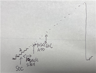
I have a project based on TIDM-DC-DC-BUCK-DC-DC Synchronous Buck Converter. The flow of the program is shown in the chart:

1. EPWM is set to up counting by     EPWM_setTimeBaseCounterMode(BUCK_DRV_EPWM_BASE, EPWM_COUNTER_MODE_UP);

2. ADC conversion is triggered at the second clock of the PWM cycle,  EPWM_setCounterCompareValue(BUCK_DRV_EPWM_BASE,EPWM_COUNTER_COMPARE_B,EPWM_ADC_TRIGGER_TBCTR);

3. It takes 10 sysclc(also PWM clock) for sample and hold; it takes 10.5x2 pwm clc to convert, because the pre-scale for ADC is 2;

 ADC_setupSOC(VOUT_ADC_MODULE,VOUT_ADC_SOC_NO,VOUT_ADC_TRIG_SOURCE,VOUT_ADC_PIN,VOUT_ADC_ACQPS_SYS_TICKS);

4. at the EOC, InterruptServiceRouting is triggered. In ISR() function, the first thing is to check the pwm counter number     isrEnter_ticks = EPWM_getTimeBaseCounterValue(BUCK_DRV_EPWM_BASE);

Based on the 4 steps above, my estimation of isrEnter_ticks should be 2+10+21=33, however, the result i got is 370(when switching frequency is set to 200kHz, which means PWM period counter is set to 500), and i got 270(when switching frequency is set to 250kHz, which means PWM period counter is set to 400). 

I didn't change the values from the demo project TIDM-DC-DC-BUCK-DC-DC, you can check the parameter values assigned to the functions.

Can you help me on this?

  • Hi Shengnan,

    Are you using RELEASE or DEBUG build for this project? If you use DEBUG, there is additional aserts which are added to function calls which can add some CPU overhead, but is helpful for checking your configuration. You can try enabling the RELEASE build (and removing the DEBUG predefined variable) and try comparing the measured cycles. 

    Also, are you running using the RAM build or FLASH build? There can be differences in execution time depending on this

    Regards,

    Peter

  • Hi, Peter, 

    I was using DEBUG and FLASH. I understand they could add overhead, but I would assume the difference is a few cycle or tens of cycles. However, what confuse me is, if i change the Period Counter to 10,000(10kHz switching frequency, with 100MHz system clock), the  isrEnter_ticks value is more than 9800. Any way, the ISR occurs at the end of the switching period instead of the beginning of the period, no matter how large the Period set to. And I am also watching the tick number at the end of ISR, isrExit_ticks, it is always a small number like 45, indicating a new switching cycles began. 

  • Hi Shengnan,

    Thank you for your patience and apologies for the delayed response.

    Yes I would not expect DEBUG to be a drastic change, but it is always best to run the RELESE build when trying to calculate the clock cycles in the most accurate way possible.

    Are you able to make use of a profiling GPIO to help visualize the length of time that the ISR is taking with respect to the switching of the EPWMs? We employ something similar on our newer reference designs, like TIDA-10062, such that we toggle high a GPIO when entering the ISR and then toggle low when exiting, and this can help to visualize on a scope. 

    Regards,

    Peter