This thread has been locked.

If you have a related question, please click the "Ask a related question" button in the top right corner. The newly created question will be automatically linked to this question.

TMS320F28034: Problems of FOC of 3-phase induction motors.

Part Number: TMS320F28034
Other Parts Discussed in Thread: CONTROLSUITE

Hi,

I'm working on a project with FOC of 3-phase induction motors. We designed the PCB based on TMS320F28034 by ourselves not use the TI development kits.

I imported the following project and do some test.

C:\ti\controlSUITE\development_kits\HVMotorCtrl+PfcKit_v2.0\HVACI_Sensorless

I encounterd severl problems and want to ask you about them.

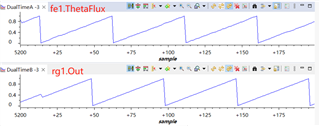
The 1st problem is that I did level 2 test and the waveform of Clark transformation is not smooth enough,

The setting is as below.

VdTesting = _IQ(0.07);

VqTesting = _IQ(0.07);

SpeedRef  = _IQ(0.4);

The system current arrived at minimum and the speed arrived at the expected one under the above settings.

Does this waveform meet the requirements?

The waveform in the doc. Sensorless Field Oriented Control of 3-Phase Induction Motors.pdf is very smooth.

If I want to get more smooth waveform, should I adjust the parameters of VdTesting and VqTesting? Or is it hardware related?

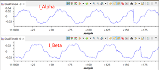
The 2nd problem is that I can't adjust a proper value of kp and ki to make the motor work normally.
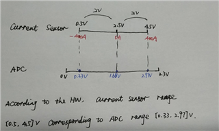
IdRef   = _IQ(0.025);

IqRef   = _IQ(0.005); 

SpeedRef  = _IQ(0.4);

IdRef and IqRef is the output of Park transformation in level 2 test when SpeedRef is 0.4. They are vibrating all the time, not stable values, is this normal?

I tried a lot of Kp and Ki values, but the PI output D_Out and Q_Out can't arrive the value(_IQ(0.07)) of VdTesting and VqTesting in level 2 test.

These two values are less than _IQ(0.07), so the motor could not be drived.

The motor can be drived if I set the IdRef and IqRef even bigger, but the output of PI is the maximum value I set, and the difference between Ref and Fbk is too big. I don't think it is a normal state.

Would you please give me some suggestions about PI regulator?

Is there anything else can I do to sovle these problems?

Waiting for your reply.

Best regards,

Sarah

  • Hello,

    Due to US holiday, please expect a response by 20th February.

    Thanks & Regards,

    Sinchita

  • Level 2 doesn't implement any PI/PID for speed and current control. You may try to tune the VdTesting, VqTesting, and SpeedRef to make the motor spinning smoothly. Don't add the load to the motor and add the right dc-bus voltage according to the spec. of the motor.

  • Hi Yanming,

    Sorry about the confusion.

    The first problem is I can't get smooth waveform of phaseA and phaseB current in Level 2 test, please look at the first screenshot. Does this have an impact  on Level 3 test?

    The second problem is I can't set proper IdRef, IqRef, kp, and ki to drive the motor work nomally at Level 3 test.

    I set the IdRef equal to the output of Park transformation Ds, and IqRef equal to the output of Park transformation Qs. I wonder if the method is right to set IdRef and IqRef. If this method is wrong, how to set these two parameters?

    Waiting for your reply.

    Best regards,

    Sarah

  • Hi Yanming,

    I have another question. We use current sensor to get the phase current, not sampling resistor used in TMDSHVMTRPFCKIT.

    Our current sensor range is [-400, 400]A, corresponding voltage is [0.5, 4.5]V

    I haven't found the value of resistances used in TMDSHVMTRPFCKIT.

    How to modify AD values for Clark transformation input?

    clarke1.As = _IQmpy2(_IQ12toIQ(AdcResult.ADCRESULT1)-offsetA); // Phase A curr.
    clarke1.Bs = _IQmpy2(_IQ12toIQ(AdcResult.ADCRESULT2)-offsetB); // Phase B curr.
    CLARKE_MACRO(clarke1)

    Waiting for your reply.

    Best regards,

    Sarah

  • Convert the sensor output range [0.5, 4.5]V to ADC input range (0~3.3V), and set the BASE_CURRENT in "HVACI_Sensorless-Settings.h" based on the sensing peak current of the sensor.

    You don't need to change the code as you mentioned above.

  • Hi Yanming,

    Thanks for your reply. We have converted the sensor output range to ADC input range, please check the following pic.

    The sensor output range is included in the ADC input range, is it OK?

    #define BASE_CURRENT    10          // Base peak phase current (amp)

    The original base current value is 10A, does it mean 3.3V corresponding to 10A in TMDSHVMTRPFCKIT?

    The comment says this is the maximum phase current, but you suggest me setting it to current sensor's peak value.

    Is it related to the motor's rated current(57A) or the range of current senor(400A)?

    If it is the current sensor's peak value, how should I set this value? 2.97V corresponding to 400A, not 3.3V.

    If possible, please pay attention to another problem from yestoday. 

    Waiting for your reply.

    Best regards,

    Sarah

  • The original base current value is 10A, does it mean 3.3V corresponding to 10A in TMDSHVMTRPFCKIT?

    Yes. The peak to peak is +/-10A, the current range of the ADC is 20A.

    If it is the current sensor's peak value, how should I set this value? 2.97V corresponding to 400A, not 3.3V.

    Convert it to map the 0~3.3V of the ADC input range.

    You should make sure the current sensing and the scaling current are correct in level 2 for level 3

  • Hi  Yanming,

    I've set the BASE_CURRENT to 400. It seems that it has no impact on AD sample results.

    I can't set proper IdRef, IqRef, kp, and ki to drive the motor work nomally at Level 3 test.

    I set the IdRef equal to the output of Park transformation Ds, and IqRef equal to the output of Park transformation Qs. I wonder if the method is right to set IdRef and IqRef. If this method is wrong, how to set these two parameters?

    Waiting for your reply.

    Best regards,

    Sarah

  • Yes, it doesn't impact ADC result, the BASE_CURRENT is useful for scaling the ADC result to PU for estimator and current control.

    Not correct. Please take a look at the application note of the example and follow the step to run the build levels.  IdRef and IqRef are the reference current for the d&q-axis current PI controllers.

  • Hi Yanming,

    The steps of application note for level 3 as below. Please check my questions in red font.

    Not correct. Please take a look at the application note of the example and follow the step to run the build levels.  IdRef and IqRef are the reference current for the d&q-axis current PI controllers

    The purpose of PI module is to make feedback keep track with reference. The feedback is the output Ds or Qs of Park transformation. So I set the reference IdRef and IqRef to the output Ds and Qs of Park transformation get in Level 2.

    If my method is not corret, how to set these two reference parameters? There is not any method in the application note.

    Waiting for your reply.

    Best regards,

    Sarah

  • You may take a look at the application note of the example project. The guide should have the answer to your questions. "Ixxx' means current like Idref, "Vxxx" means voltage like Vd. The value of IdRef is related to the spec. of the motor.

  • Hi Yanming,

    Thanks for your reply. I've gotten some proper parameters for Level 3, and test the speed calculation, the speed1.Speed is less than SpeddRef a little.

    At Level4, the application note said that the fe1.ThetaFlux and rg1.Out should be identical with a small phase shift, but I got a big phase shift of them, please check the below fig.

    What's the reason for this result?

    And it seems that the estimated d&q fluxes are not correct too. I didn't get sine curve in graph windows because the values are not correct. I get two vaules from watch window as below. I've modify the motor parameters in file HVACI_Sensorless-Settings.h according to our motor. Is there anything to modify to calculate the fluxes?

    Waiting for your reply.

    Best regards,

    Sarah

  • You need to set the right motor parameters for the speed&flux estimator. Please take a look at the AN that shows how to set these parameters.

  • Hi Yanming,

    I follow this document to do these tests.

    C:\ti\controlSUITE\development_kits\HVMotorCtrl+PfcKit_v2.1\HVACI_Sensorless\~Docs\Sensorless FOC of ACI.pdf

    And there is no description of parameters setting in Level4 as below fig.

    Is there any other reference document to set these parameters?

    Waiting for your reply.

    Best regards,

    Sarah

  • You can find the documentation or the estimator in the folder below.

    C:\ti\controlSUITE\libs\app_libs\motor_control\math_blocks\v4.1\~Docs