Because of the holidays, TI E2E™ design support forum responses will be delayed from Dec. 25 through Jan. 2. Thank you for your patience.

This thread has been locked.

If you have a related question, please click the "Ask a related question" button in the top right corner. The newly created question will be automatically linked to this question.

TIDM-1000: TIDM-1000 have large iTHD when the experiment of Build 4

Part Number: TIDM-1000

Hi all,

I have completed testing the TIDM-1000 from Build 1 to Build 4 and operates normally.
However, I encountered the same issue as this article. In Build 4 the iTHD is more larger than Build 3.(After disconnecting the bus voltage midpoint and the neutral point.)

e2e.ti.com/.../tms320f280049-tidm1000-balance-voltage-loop-question-large-thd

Unfortunately, there was no solution. Is there anyone who can provide some suggestions or solutions?

Regards,

Lyon

Attachment : 

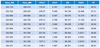
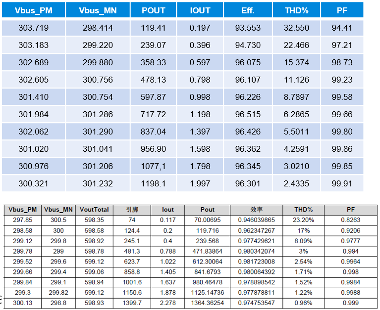
1.The table at the top is actual measurements in Build 4, the below is provided by the TIDM-1000 Design Guide.
AC input is 208Vrms L-L, 60Hz
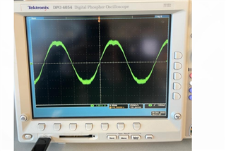
2. The current waves of build 3 and build 4

  • Hi Lyon,

    I am checking with an expert on this. 

    Yes, I agree with you build 4 should have lower iTHD compared with build 3.

    Thanks & Regards,

    Uttam

  • Hi Lyon, 

    for your build 4, I assume you followed the same procedure as mentioned in design guide. I have couple of questions: 

    1. your iTHD(build-4) looks different. Have you disabled third harmonic injection (or) balance controller?

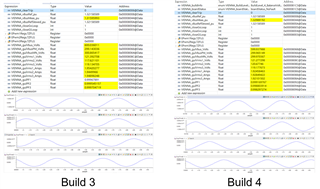
    2. Could you capture your expression window as shown below for build 3 and build 4? Share the THD seen from your end for build 3 & build 4. 

    3. Have you modified anything on the h/w or control (Kp, Ki parameters by any chance)?

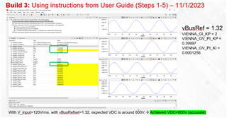
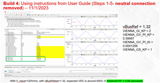
    Below waveform for reference only (Uttam)

    Regards,

    Uttam

  • +++ Here is the THD waveforms for build-4 observed at our end.

    Regards,

    Uttam

  • Hi Uttam,

    1. I didn't disable the third harmonic injection and balance controller, but when I attempted to turn third harmonic injection off, I observed that the iTHD would slightly decrease instead of increasing.

    2.The expression window is shown as below.

    3.I did not make any modifications to the control loop parameters and H/W. I only enable the VIENNA_nonLinearVoltageLoopFlag.

    In addition, the current waveform chart I initially attached, "50% load" means that IOUT is 1A (600W).

    Regards,

    Lyon

  • Hi Uttam,

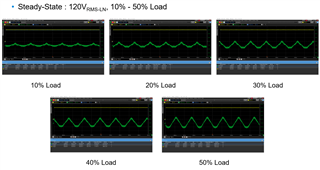
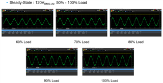
    The problem at hand is that the THD measured at VINPUT=120VRMS is worse than the specifications provided in the design guide.
    We can't do it within 1% at rated power, and the peak efficiency is only 96%.
    I attach the current waveforms under different load conditions(10%[0.2A] to 100%[2A]) for your reference.

    Regards,

    Lyon

  • Hi Lyon, 

    Thats strange, if using the same h/w and s/w the results should be very close. this design been there for a while and seen no such concerns. 

    1. Could you compare the iTHD result with 50% and 100% load on build-4 by disabling  VIENNA_nonLinearVoltageLoopFlag (since by default its disabled)? 

    Thanks & Regards,

    Uttam

  • Hi Uttam,

    I will test it tomorrow and will let you know when I have new results.Thanks.

    Regards,

    Lyon

  • Hi Uttam,

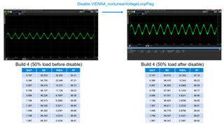
    When I disable the VIENNA_nonLinearVoltageLoopFlag, the problem of current negative half-cycle distortion has been eliminated.
    The measurement results are shown as below:

    But there are still some problems that need to be solved.

    1.Although iTHD and efficiency have improved, it still can't meet the specifications in the design guide(iTHD<1%, efficiency > 98% at rate load with 208Vrms).

    2.It was found that the current waveform of iL3 was distorted. As a result, iTHD is higher than the other two phases as shown below.

    Are there any other suggestions you can provide regarding the above issues? Thanks.

    Regards,

    Lyon

  • Hi Lyon,

    This is expected to be improved with VIENNA_nonLinearVoltageLoopFlag() disableI understand your urgency, We first need to identify the problem what is causing the deviation from specs.

    Thanks for sharing the IL waveforms. We need to figure out why only IL3 is slightly distorted in build 4. since the closed current loop is configured in build 2 and build 3, this might be coming from there. Have you observed the waveforms then?

    I would recommend obtaining the IL1, IL2, IL3 waveforms for build 2 (50% load) & build 3 (50% load) and compare the waveforms.

    Best Regards,

    Uttam

  • Hi Uttam,

    I have confirmed Build 2 and Build 3 and found that the IL3 current is not distorted. The iTHD of the three phases can reach about 1% in rated load (1200W).
    Then I re-tested Build 4 and found that distortion still occurred in IL3.
    After cross testing in Build 4, I found that when the third harmonic injection is turned off, the distortion issue in IL3 is sloved. And the three-phase iTHD can reach 1% in rated load (1200W).
    Would you have any thoughts on the results?
    Theoretically, third harmonic injection increases VBUS stability, but it is still unclear why it would cause IL3 distortion.

    So far, the problem of iTHD has been solved, but the peak efficiency is still stuck at around 97%.
    I will try adjusting the loop parameters to improve. Do you have any other suggestions? Thank you.

    Best Regards,

    Lyon

  • Hi Lyon, 

    Good to know. 

    For build 4: Theoretically, third harmonic injection increases VBUS stability, but it is still unclear why it would cause IL3 distortion. - I agree on this but why its not seen on IL2/IL1 should be identified. 

    Could you try this, swapping the input source (i.e, A,B,C phases to B,C,A) just to identify if its s/w (or) source related issue. 

    At this time I dont have any other suggestions here. Let see your observations and go from there.

    Best Regards,

    Uttam Reddy

  • Hi Uttam,

    I have tried swapping the input source before but the IL3 still have the distortion.

    I will try again after tomorrow and get back to you.

    Best Regards,

    Lyon

  • Hi Uttam,

    I am continuing to improve efficiency.
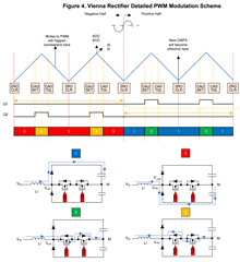
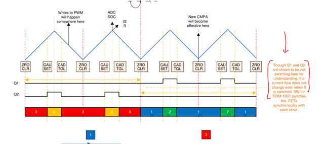
    Also I have another question. As shown in the figure, the PWM modulation method provided in the Design Guide.
    I would like to ask why the Q1 and Q2 signals in this picture are not synchronous.
    One is turning on and the other is conducting through the body diode.
    Does it have any special meaning? Thank you.

    Best Regards,

    Lyon

  • Hi Lyon,

    I dont think making it synchronous helps in current direction. please refer to this note on the design guide

    Regards,

    Uttam

  • Hi Uttam,

    OK, thanks.
    Going back to the issue of efficiency, are there any other ways to improve efficiency besides modifying the hardware?
    Because the PF is already very good, modifying the current and voltage looop seems to have a very low impact on efficiency.
    Do you have the latest measured efficiency table for reference? Thank you.

    Regards,

    Lyon

  • Hi Lyon,

    Since the deviation of efficiency is very low (almost 1.1%) at full load, the only thing i could think of is by hardware. One thing you might be interested to check on the efficiency estimates sheet and compare to your hardware setup. Good to see where the losses might be happening in your h/w setup. 

    I have only tested the PF recently but not the efficiency estimates. Images are already shared above.

    In my opinion, fixing the deviation in the current waveform discussed earlier could bring better efficiency. 

    Thanks & Regards,

    Uttam

  • Hi Uttam,

    The current situation is that when the third harmonic injection is turned off, there is no current waveform deviation in build1/2/3/4.
    Both iTHD and PF are in good condition.
    So I still don’t know how to solve it. I will check the hardware part first.
    If there are any other new findings, I will open a new question to discuss with you.
    Thank you for your help.

    Regards,

    Lyon