This thread has been locked.

If you have a related question, please click the "Ask a related question" button in the top right corner. The newly created question will be automatically linked to this question.

TMS320F28P650DK: Motor control tuning on the UMCL project

Part Number: TMS320F28P650DK
Other Parts Discussed in Thread: DRV8353RS-EVM, SFRA, LAUNCHXL-F28P65X

Hi,

I am working on the Universal Motor Control Lab project, with the f28p65x LaunchPad and the DRV8353RS-EVM boards.

I follow the instructions of the SPRUJ26 user's guide

I have passed DMC_LEVEL1 up to DMC_LEVEL3 without any problem.

At DMC_LEVEL4 (9.b. page 84 of SPRUJ26), I have two problems.

The first one is that there is a startupFailed flag, that means I can't reach the colesd loop speed control with my motor and the rotor keeps spinning at really low speed.

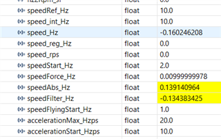
The second one is that, when the rotor keeps spinning at very low speed, there a scale factor of around 4 between the speed value that I can read (speed_Hz = 0.008 => 0.48rpm) and the physical speed (2rpm).

I think there is a problem in my motor parameters (in user_mtr1.h).

Do you have a user's guide that details how to set the motor parameters correctly and tune the controllers please?

Thanks a lot in advance for your help.

David

  • Hi David,

    1. Are you using sensored/sensorless method?

    2. If you are using sensorless method, the motor parameters must be accurate for the speed estimator to work, and you can verify this in build level #2.

    3. If the motor parameters are not available, you can try to run motor identification.

    Thanks,

    Jiaxin

  • Hi Jiaxin,

    For the moment I am using sensorless method.

    In Level2, my motor spins but not at the good speed (speedRef_Hz=10, speedForce_Hz=0.01 and physical speed=20rpm).

    My motor is a 15 pole pairs PMSM.

  • During the identification procedure in Level 4, it seems that Ls_d_H and Ls_q_H cannot be calculated (I obtained 9.9999e-07, but the physical value is 0.00032).

    However RoverL_rps is close to the physical value (Rs_Ohm=0.18):

    I have tried to change the USER_M1_R_OVER_L_EXC_FREQ_Hz define value without any success.

  • Hi David,

    In Level2, my motor spins but not at the good speed (speedRef_Hz=10, speedForce_Hz=0.01 and physical speed=20rpm).

    Could you explain more on this? In the screenshot, it seems the actual speed doesn't match the reference speed. Meanwhile, if the motor pole pairs is 15, the physical speed should be 40rpm given reference frequency 10Hz.

    During the identification procedure in Level 4, it seems that Ls_d_H and Ls_q_H cannot be calculated (I obtained 9.9999e-07, but the physical value is 0.00032).

    How did you get the physical value? "Ls_d_H" and "Ls_q_H" should be the stator inductance on the d,q-axis.

     Thanks,

    Jiaxin

  • My motor keeps spinning physically at 20rpm in level2 and level3, with a speedRef at 10Hz.

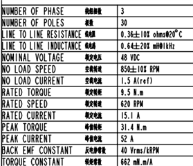
    The motor manufacturer gives the line to line inductance in the motor datasheet:

  • Hi David,

    My motor keeps spinning physically at 20rpm in level2 and level3, with a speedRef at 10Hz.

    Yes. But with 15 pole pairs, the synchronous speed should be 40 rpm.

    The motor manufacturer gives the line to line inductance in the motor datasheet:

    The equivalent "Ls_d_H" and "Ls_q_H" are not directly accessible from the motor spec, you need to have the motor's dynamic model in the d,q frame to get them.

    Thanks,

    Jiaxin

  • I agree for the speed, that is why I need your help.

    Regarding the Ld and Lq values, they are normally close to Ls or L0, it is not possible to have Ls=0.00032H and Ld=Lq=9.9e-07H. What paramter do I have to adjust if the Ld Lq is under estimated please?

    Best regards,

    David

  • Ls=0.00032H

    Typically enter the same value for Ld user_motor1.h as you did for Lq. Often have to tweak (reduce) inductance a few hundred µH rotor to reach top speed without vibrations. The wait times of motor ID process (Ld/Lq) flux calculation may be due to the ADC PPB and data window combinations. We had to tweak the Ld/Lq flux wait times to stop 9.9e-07H, reset default parameter values.

    user_motor1.c

    pUserParams->LsWaitTime[EST_LS_STATE_ERROR] = 0;
    pUserParams->LsWaitTime[EST_LS_STATE_IDLE] = 0;
    pUserParams->LsWaitTime[EST_LS_STATE_RAMPUP] = (int_least32_t)(10.0 * USER_M1_ISR_FREQ_Hz); //10.0
    pUserParams->LsWaitTime[EST_LS_STATE_COARSE] = (int_least32_t)(25.0 * USER_M1_ISR_FREQ_Hz); //30.0
    pUserParams->LsWaitTime[EST_LS_STATE_FINE] = (int_least32_t)(25.0 * USER_M1_ISR_FREQ_Hz); //30.0
    pUserParams->LsWaitTime[EST_LS_STATE_DONE] = 0;

    defaults:

    pUserParams->Ls_d_H = (float32_t)1.0e-6;
    pUserParams->Ls_q_H = (float32_t)1.0e-6;
    pUserParams->Ls_coarseDelta_H = (float32_t)0.0000001f;
    pUserParams->Ls_fineDelta_H = (float32_t)0.00000001f;
    pUserParams->Ls_min_H = (float32_t)0.000001f;
    pUserParams->Ls_max_H = (float32_t)100.0f;

  • Hi David,

    I agree for the speed, that is why I need your help.

    If the speed was the same for build level 2 and build level 3, it seems the open loop control in build level 2 doesn't work as expected as the actual speed is not following the given reference. Did you verify that in build level 2, the voltage and current feedback signals are correct before continuing?

    In build level 2, did you modify the motor's v/f profile to match the motor you have?

    Thanks,

    Jiaxin

  • Hi Jiaxin,

    Thanks a lot, now I have more realistic value for Ld Lq after following your suggestions.

    So now my motor spins in closed loop of speed (level4), and speed_Hz follows speedRef_Hz, but the physical speed is always half the speedRef. Do you have any idea to solve that problem?

    How can I use SFRA tool to tune my controllers please? my project is the Universal Motor Control Lab and it seems to integrate that tool but I don't how to use it.

  • Hi David,

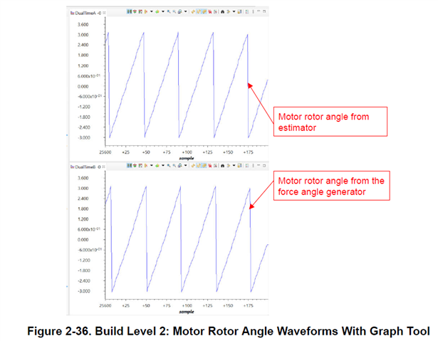
    In build level 2, did you check if the actual angular speed matches the estimated angular speed?


    The SFRA functions are not directly included through changing the build levels in the universal motor control lab, but you could refer to other projects which has build level with SFRA and add the functions into your software.

    Thanks,

    Jiaxin

  • Thank you Jiaxin for your reply!

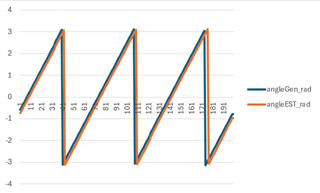
    I have used datalog.iptr[0]=motorVars_M1.angleGen_rad and datalog.iptr[0]=motorVars_M1.angleEST_rad.

    I didn't reach to use the Graph tool to see datalogBuff1 and datalogBuff2 contents, but I extract them to an Excel file and I confirm that angleEST_rad and angleGen_rad are quite the same @ speedRef_Hz=30.0

    But the physical speed of the rotor is 60rpm there (that motor has a 15 pole pairs).

  • I also see a weird thing with the same type of scale factor of 0.5.

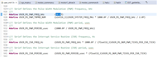
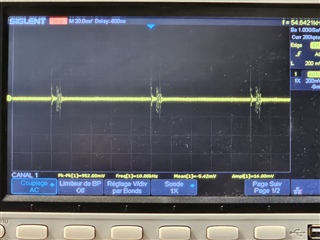
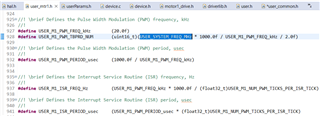
    I configure USER_M1_PWM_FREQ_kHz to 20.0, but I see on the oscilloscope a communation frequency of 10kHz:

  • The picture look good.

  • Hi David,

    Let me think about it.

    Thanks,

    Jiaxin

  • Hi Jiaxin,

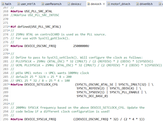
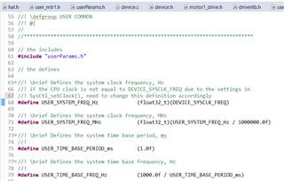
    I have an idea. I wonder if my dual problem would be due to a bad CPU clock frequency settings.I use a LAUNCHXL-F28P65X (with a 25MHz oscillator).

    Please find below my settings:

  • Hi David,

    You can confirm the PLL and SYSCLK speed via GPIO port after configuring XCLKOUT divisor.

        /* Select XCLKOUT source is SYSCLK */
        SysCtl_selectClockOutSource(SYSCTL_CLOCKOUT_PLLSYS); //SYSCTL_CLOCKOUT_SYSCLK
        /* Set XCLKOUT divider for 25MHz Signal
         * using GPIO_16_XCLKOUT J2-15 */
        SysCtl_setXClk(SYSCTL_XCLKOUT_DIV_4);
        
        // x49C MCU
        // GPIO16->SPIA-SDI for J1/J2 connection
        // XCLOCK_OUT test INTOSC1 J2-pin 15
        GPIO_setMasterCore(16, GPIO_CORE_CPU1);
        GPIO_setPinConfig(GPIO_16_XCLKOUT); //GPIO_16_SPISIMOA
        GPIO_setDirectionMode(16, GPIO_DIR_MODE_OUT);
        GPIO_setPadConfig(16, GPIO_PIN_TYPE_STD);
        GPIO_setQualificationMode(16, GPIO_QUAL_ASYNC);    
        

  • David,

    How did you measure the actual speed in RPM of the motor?

    Thanks,

    Jiaxin

  • Hi Jiaxin,

    I measure the actual speed in RPM counting the number of rounds the rotor makes in one minute.

  • Hi David,

    I didn't aware of any problem in the motor's speed since the estimated angle and the given angle matches each other. You can double verify this through the frequency of current waveform. Probably there is something wrong with the actual speed RPM measurement.

    Thanks,

    Jiaxin