This thread has been locked.

If you have a related question, please click the "Ask a related question" button in the top right corner. The newly created question will be automatically linked to this question.

TMS320F280049C: TIDM-1000 Compensation design using SFRA data

Part Number: TMS320F280049C
Other Parts Discussed in Thread: TIDM-1000, SFRA

Hi Team,
Greetings of the day!.

We are designing custom PFC board and referring the Design Guide TIDM-1000 of Vienna Rectifier. We have a doubt on the TIDM-1000 compensation designer tool Using C2000 MCU (F280049C EVM).

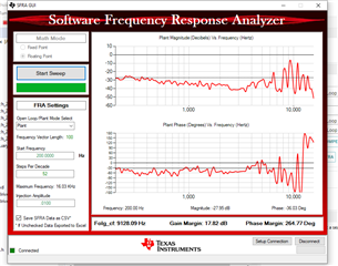
We have captured SFRA data in Build level-1 with custom board at 30VAC input with 50% duty cycle and we are getting SFRA data as attached in below.


1. Do we need to run in all builds (1 to 4) to capture SFRA data for Compensation Designer?
(or)
2. Is Open loop SFRA data captured for Compensation Designer, sufficient for Current Loop and V&I Loop?

Thank you.

  • Your understanding seems to be about right.SFRA just measures the plants response.

    It is typical to use it to develop a model of your plants response. Then to use that plant model in compensation designer to adjust controller variables. Then finally rerunning SFRA on hardware while the new compensator is running such that you can verify your phase and gain margin.

    Regards,
    Cody 

  • Hi Cody,

    Thanks for the Reply!

    We will rerun the SFRA on hardware and will verify the phase and gain margin.

    Thanks & Regards,

    Chaithanya

  • Hi Cody,

    We are using the plant model in compensation designer, to adjust controller variables in closed current loop (i.e., Build-level-2). We are rerunning SFRA on the same hardware with the new compensation value (KP = 6).


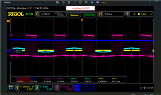
    We have set KP = 6 as per Compensation results we got in the previous run. But not getting the set Reference Current (IRef = 0.6A) as shown in the below results.

    Test condition:

    Input Voltage = 30VAC, Load-R = 500 ohms, IRef = 0.6A

    DSO Image:

    Yellow: R -Phase current (50mv/A)

    Blue: R-Phase voltage

    Pink: PWMRH

    Dark Blue: DCBUS voltage

    Pls verify the phase and gain margin for the above graph.

    Thanks & Regards,

    Chaithanya N.

  • Working with the assumption that you are confident in the PWM outputs in open-loop mode:

    I can't really tell what the phase current is doing in the graph, but it looks close to zero. If you're not getting any control over the output I would start by debugging the controller's output and ensure that its outputting as suspected and not being clamped. If that is working see if that is correctly propagating to the PWM outputs.

    If the controller is not correctly outputting control values then the controller may be poorly tuned. I would consider manually tuning the variables to get it running then applying SFRA to refine. I would be cautious about doing this on hardware, Make sure all over-voltage/ over-current trips are setup and tested working.


    Regards,
    Cody