This thread has been locked.

If you have a related question, please click the "Ask a related question" button in the top right corner. The newly created question will be automatically linked to this question.

TMS320F28027F: Master (TMS320F28027) writing 3 bytes in SPI (3-wire mode) to an slave

Part Number: TMS320F28027F
Other Parts Discussed in Thread: DAC70501

Hi everyone, 

I having problems to configure the SPI 3-wire mode, to simply send 3 bytes to an SPI slave. 

The GPIOs are correctly configured:

SysCtrlRegs.PCLKCR0.bit.SPIAENCLK = 1;	// SPI-A
//--------------------------------------------------------------------------------------
//  GPIO-16 - PIN FUNCTION = SPISIMO-A
	GpioCtrlRegs.GPAPUD.bit.GPIO16 = 0;   // Enable pull-up on GPIO16 (SPISIMOA)
	GpioCtrlRegs.GPAQSEL2.bit.GPIO16 = 3; // Asynch input GPIO16 (SPISIMOA)
	GpioCtrlRegs.GPAMUX2.bit.GPIO16 = 1;	// 0=GPIO,  1=SPISIMO-A,  2=Resv,  3=TZ2
//--------------------------------------------------------------------------------------
//  GPIO-17 - PIN FUNCTION = SPISOMI-A (as GPIO not needed in 3-wire mode)
	GpioCtrlRegs.GPAMUX2.bit.GPIO17 = 0;	// 0=GPIO,  1=SPISOMI-A,  2=Resv,  3=TZ3
	GpioCtrlRegs.GPADIR.bit.GPIO17 = 1;		// 1=OUTput,  0=INput
	GpioDataRegs.GPACLEAR.bit.GPIO17 = 1;	// uncomment if --> Set Low initially
//--------------------------------------------------------------------------------------
//  GPIO-18 - PIN FUNCTION = SPICLK-A
	GpioCtrlRegs.GPAPUD.bit.GPIO18 = 0;   // Enable pull-up on GPIO18 (SPICLKA)
	GpioCtrlRegs.GPAQSEL2.bit.GPIO18 = 3; // Asynch input GPIO18 (SPICLKA)
	GpioCtrlRegs.GPAMUX2.bit.GPIO18 = 1;	// 0=GPIO,  1=SPICLK-A,  2=SCITX-A,  3=XCLKOUT
//--------------------------------------------------------------------------------------
//  GPIO-19 - PIN FUNCTION = SPISTE-A
	GpioCtrlRegs.GPAPUD.bit.GPIO19 = 0;   // Enable pull-up on GPIO19 (SPISTEA)
	GpioCtrlRegs.GPAQSEL2.bit.GPIO19 = 3; // Asynch input GPIO19 (SPISTEA)
	GpioCtrlRegs.GPAMUX2.bit.GPIO19 = 1;	// 0=GPIO,  1=SPISTE-A,  2=SCIRX-A,  3=ECAP1
//--------------------------------------------------------------------------------------

Then I initialised the FIFO with 3 levels for TX, I do not need RX (or maybe yes?): 

void spi_fifo_init()
{
// Initialize SPI FIFO registers
    //SpiaRegs.SPIFFTX.all=0xE040;
    SpiaRegs.SPIFFTX.bit.SPIRST=1;      //SPI FIFO can resume transmit or receive
    SpiaRegs.SPIFFTX.bit.SPIFFENA=1;    //SPI FIFO enhancements are enabled
    SpiaRegs.SPIFFTX.bit.TXFFINTCLR =1; // Clear TXFIFO interrupt flag
    SpiaRegs.SPIFFTX.bit.TXFFIENA = 0;  // TXFIFO interrupt disabled
    SpiaRegs.SPIFFTX.bit.TXFFIL =3;     //3 levels for TXFIFO Interrupt (no needed)
    SpiaRegs.SPIFFTX.bit.TXFIFO =1;     //Release transmit FIFO from reset.

    //SpiaRegs.SPIFFRX.all=0x2044;

    SpiaRegs.SPIFFRX.bit.RXFFOVFCLR = 1;   // CLEAR OV rX flag
    SpiaRegs.SPIFFRX.bit.RXFFINTCLR =1;     //b6 Clear SPIFFRX flag
    SpiaRegs.SPIFFRX.bit.RXFFIENA = 0;      //b5 RXFIFO interrupt disabled
    SpiaRegs.SPIFFRX.bit.RXFFIL=0;          //level bits for RXFIFO Interrupt (no needed)
    SpiaRegs.SPIFFRX.bit.RXFIFORESET = 1;   //b13 Re-enable receive FIFO operation.

    SpiaRegs.SPIFFCT.all=0x0;               //The next word in the TX FIFO buffer is transferred to
                                            //SPITXBUF immediately upon completion of transmission of the
                                            //previous word.
}

Then SPI initialisation :

void spi_init_DAC70501()
{
    //SpiaRegs.SPICCR.all =0x000F;                 // Reset on, rising edge, 16-bit char bits


    //SpiaRegs.SPICTL.all =0x0006;                 // Enable master mode, normal phase,
                                                 // enable talk, and SPI int disabled.
    SpiaRegs.SPICCR.bit.SPISWRESET = 0; //Reset SPI before configuration
    SpiaRegs.SPICCR.bit.CLKPOLARITY =1; //falling edge
    SpiaRegs.SPICCR.bit.SPICHAR =7; //8-bit char bits


    SpiaRegs.SPICTL.bit.MASTER_SLAVE=1; //Enable master mode
    SpiaRegs.SPICTL.bit.CLK_PHASE=1; // phase with delay
    SpiaRegs.SPICTL.bit.TALK = 1;    // Enable Transmit path
    SpiaRegs.SPICTL.bit.OVERRUNINTENA = 0; //disbale overrun interruption
    SpiaRegs.SPICTL.bit.SPIINTENA = 0;     ////disable SPIinterruption

    SpiaRegs.SPIBRR =127;   // SPI Baud Rate=LSPCLK/(SPIBRR+1)  LSPCLK=CPU_FREQ/4
                                // 15MHz/(127+1)=117kHz
                                // 15MHz/(14+1)=1MHz
    SpiaRegs.SPIPRI.bit.TRIWIRE=1; //3-wire SPI mode enable
                                   //(The unused pin SPISOMI is free for GPIO)

    //SpiaRegs.SPICCR.all =0x009F;                 // Relinquish SPI from Reset
    SpiaRegs.SPICCR.bit.SPISWRESET = 1;           // Relinquish SPI from Reset
    SpiaRegs.SPIPRI.bit.FREE = 1;                // Set so breakpoints don't disturb xmission


}

And finally this is the TX function I am periodically calling  in the main program:

/**********************************************************************
* Function: spi_xmit()
*
* Description: Transmit 16bit to SPIA using 3-Wire Mode Transmit
* When the master transmits, it receives the data it
* transmits (because SPISIMOx and SPISOMIx are connected
*  internally in 3-wire mode). Therefore, the junk data received
*  must be cleared from the receive buffer every time data is transmitted.
**********************************************************************/
void spi_xmit(char a)
{

Uint16 data= (Uint16)(a<<8);
Uint16 dummy;

    SpiaRegs.SPICTL.bit.TALK = 1; // Enable Transmit path
    SpiaRegs.SPITXBUF = data; // Master transmits data
    while(SpiaRegs.SPISTS.bit.INT_FLAG !=1) {} // Waits until data rx’d
    dummy = SpiaRegs.SPIRXBUF; // Clears junk data from itself
    SpiaRegs.SPITXBUF = data; // Master transmits data
    while(SpiaRegs.SPISTS.bit.INT_FLAG !=1) {} // Waits until data rx’d
    dummy = SpiaRegs.SPIRXBUF; // Clears junk data from itself
    SpiaRegs.SPITXBUF = data; // Master transmits data
    while(SpiaRegs.SPISTS.bit.INT_FLAG !=1) {} // Waits until data rx’d
    dummy = SpiaRegs.SPIRXBUF; // Clears junk data from itself
}

I can check in the oscilloscope that the 1st byte is sent but the communication gets block after that. 

Without 3-wire mode or FIFO, I am able to send 2bytes without problems (no blocking). 

What I am doing wrong? What is the right way to simply send 3 bytes by SPI to an external slave ?

Thanks in advance. 

Best regards 

  • Hello,

    When you say that communication is "blocked", do you mean that the code is stuck in the "while" loop waiting for the INT_FLAG to set to 1? Or perhaps could you elaborate on the meaning?

    Can you also please provide some oscilloscope captures of the behavior on the SPI lines as well so we can view the behavior?

    Allison

  • Hi Allison, 

    Yes, you were right, the blocking was due to the line:

    while(SpiaRegs.SPISTS.bit.INT_FLAG !=1) {} // Waits until data rx’d

    Removing it I can see the 3 bytes are send properly.

    void spi_xmit(char a)
    {
    
        SpiaRegs.SPICTL.bit.TALK = 1; // Enable Transmit path
        SpiaRegs.SPITXBUF = (Uint16)(0x03<<8); // Master transmits data
        dummy = SpiaRegs.SPIRXBUF; // Clears junk data from itself
        SpiaRegs.SPITXBUF = (Uint16)(0x01<<8); // Master transmits data
        dummy = SpiaRegs.SPIRXBUF; // Clears junk data from itself
        SpiaRegs.SPITXBUF = (Uint16)(0x00<<8); // Master transmits data
        dummy = SpiaRegs.SPIRXBUF; // Clears junk data from itself
    }

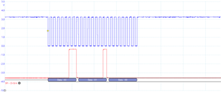
    Data (red ) and clock (blue)

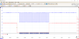
    SPISTE line (red) and clock (blue). 

    It looks like now is sending the 3 bytes correctly. However the DAC (SPI slave) seems to not be reacting. Could it be the polarity and phase of the SPI? From the DAC specs I thought it was falling edge with delay. Could it be wrong? 

    Thanks for your help 

    Best regards 

  • Hi,

    Glad to hear the data seems to be sending correctly! Just to explain a bit:

    • If you are not using FIFO, the SPISTS bit can be used to detect if the transmission is complete.
      • Since you are in FIFO mode but trying to use SPISTS, I believe this is why you were getting hung up in that 'while' loop
    • If you are using FIFO, you can use the SPIFFRX.RXFFST to detect when the SPI has completed transmitting. Since the SPI is a shift register, when the receiver has received the expected number of data, you know that the transmitter has completely transmitted the data.

    It is generally best practice to check one of these (depending on if you are in FIFO vs. nonFIFO mode) to ensure transmissions are not overwritten/corrupted Slight smile

    In regards to the clocking, from the image you attached it looks to me like the data is being transmitted on the rising edge of the clock and latched on the falling edge of the clock, which would indicated that the F28027 clock polarity should be 0 and phase should be 0. From the device TRM section 8.3.6 SPI Clocking Schemes, this would be "Rising Edge Without Delay. The SPI transmits data on the rising edge of the SPICLK signal and receives data on the falling edge of the SPICLK signal." Let me know if using the clock mode changes the behavior! 

    Best Regards,

    Allison

  • Hi Allison, 

    You were right about the clock polarity and phase. It is working perfectly now with "Rising Edge Without Delay".

    About the SPI configuration I would copy paste my final configuration, to help other users and also to clarify some doubts. My goal was to transmit as master 3 bytes to a SPI slave (in this case the DAC 70501):

    1. Configure SPI pin and enable the SPI clock 

    The GPIO are configured for SPI 3-wire (GPIO-17 is free for other uses)  : 

    -GPIO-16 - PIN FUNCTION = SPISIMO-A

    -GPIO-18 - PIN FUNCTION = SPICLK-A

    - GPIO-19 - PIN FUNCTION = SPISTE-A

    2.SPI FIFO config:

    /**********************************************************************
    * Function: spi_fifo_init_DAC70501()
    *
    * Description: Sets the SPI fifo configuration for the DAC70501
    * - Enable FIFO enhancement
    * - No interruptions
    **********************************************************************/
    void spi_fifo_init_DAC70501()
    {
    // Initialize SPI FIFO registers
        //SpiaRegs.SPIFFTX.all=0xE040;
        SpiaRegs.SPIFFTX.bit.SPIRST=1;      //SPI FIFO can resume transmit or receive
        SpiaRegs.SPIFFTX.bit.SPIFFENA=1;    //SPI FIFO enhancements are enabled
        SpiaRegs.SPIFFTX.bit.TXFFINTCLR =1; // Clear TXFIFO interrupt flag
        SpiaRegs.SPIFFTX.bit.TXFFIENA = 0;  // TXFIFO interrupt disabled
        SpiaRegs.SPIFFTX.bit.TXFFIL =0;     //levels for TXFIFO Interrupt (no needed)
        SpiaRegs.SPIFFTX.bit.TXFIFO =1;     //Release transmit FIFO from reset.
    
        //SpiaRegs.SPIFFRX.all=0x2044;
        SpiaRegs.SPIFFRX.bit.RXFFOVFCLR = 1;   // CLEAR OV rX flag
        SpiaRegs.SPIFFRX.bit.RXFFINTCLR =1;     //b6 Clear SPIFFRX flag
        SpiaRegs.SPIFFRX.bit.RXFFIENA = 0;      //b5 RXFIFO interrupt disabled
        SpiaRegs.SPIFFRX.bit.RXFFIL=0;          //level bits for RXFIFO Interrupt (no needed)
        SpiaRegs.SPIFFRX.bit.RXFIFORESET = 1;   //b13 Re-enable receive FIFO operation.
    
        SpiaRegs.SPIFFCT.all=0x0;               //The next word in the TX FIFO buffer is transferred to
                                                //SPITXBUF immediately upon completion of transmission of the
                                                //previous word.
    }
    

    2.SPI config:

    /**********************************************************************
    * Function: spi_init_DAC70501()
    *
    * Description: Initializes spi on the piccolo for DAC70501 SPI specs
    * - CLOCK polarity and Phase:
    *    data is being transmitted on the rising edge of the clock and latched
    *    on the falling edge of the clock, which would indicated that the F28027
    *    clock polarity should be 0 and phase should be 0.
    *    From the device TRM section 8.3.6 SPI Clocking Schemes, this would be
    *    "Rising Edge Without Delay.
    *    The SPI transmits data on the rising edge of the SPICLK signal and
    *    receives data on the falling edge of the SPICLK signal."
    *  - 8 bit char--> each transmitted word is configured to be a byte (8 bits)
    *  - 3-wire SPI mode enable:
    *       When the master transmits, it receives the data it
    *       transmits (because SPISIMOx and SPISOMIx are connected
    *       internally in 3-wire mode). Therefore, the junk data received
    *       must be cleared from the receive buffer every time data is transmitted.
    
    * GPIOs are initialised in Gpio.c and CLOCKs in InitSysCtrl()
    **********************************************************************/
    void spi_init_DAC70501()
    {
        //SpiaRegs.SPICCR.all =0x000F;                 // Reset on, rising edge, 16-bit char bits
    
    
        //SpiaRegs.SPICTL.all =0x0006;                 // Enable master mode, normal phase,
                                                     // enable talk, and SPI int disabled.
        SpiaRegs.SPICCR.bit.SPISWRESET = 0; //Reset SPI before configuration
        SpiaRegs.SPICCR.bit.CLKPOLARITY =0; //rising edge
        SpiaRegs.SPICCR.bit.SPICHAR =7; //8-bit char bits
    
    
        SpiaRegs.SPICTL.bit.MASTER_SLAVE=1; //Enable master mode
        SpiaRegs.SPICTL.bit.CLK_PHASE=0; // phase without delay
        SpiaRegs.SPICTL.bit.TALK = 1;    // Enable Transmit path
        SpiaRegs.SPICTL.bit.OVERRUNINTENA = 0; //disbale overrun interruption
        SpiaRegs.SPICTL.bit.SPIINTENA = 0;     ////disable SPIinterruption
    
        SpiaRegs.SPIBRR =14;        // SPI Baud Rate=LSPCLK/(SPIBRR+1)  LSPCLK=CPU_FREQ/4
                                    // 15MHz/(127+1)=117kHz
                                    // 15MHz/(14+1)=1MHz
        SpiaRegs.SPIPRI.bit.TRIWIRE=1; //3-wire SPI mode enable
                                       //(The unused pin SPISOMI is free for GPIO)
    
        //SpiaRegs.SPICCR.all =0x009F;                 // Relinquish SPI from Reset
        SpiaRegs.SPICCR.bit.SPISWRESET = 1;           // Relinquish SPI from Reset
        SpiaRegs.SPIPRI.bit.FREE = 1;                // Set so breakpoints don't disturb xmission


    3. SPI transmit function/s :

    /**********************************************************************
    * Function: DAC70501_setVoltage_SPI()
    *
    * Description: Sets the output voltage to a fraction of source vref.  (Value
                can be 0..16383  (0-0x3FFF))
                output:
                    The 14-bit value representing the relationship between
                    the DAC's input voltage and its output voltage.
    
    **********************************************************************/
    void DAC70501_setVoltage_SPI(uint16_t output)
    {
    uint16_t data;
    uint16_t dummy;
    
        data = (uint16_t)(output<<2);     //shift to the left DAC_data reads 14bits left-aligned
    
    char byte1=DAC70501_DAC_DATA;           //command value in this case 0x08
    char byte2=(char) ((data >> 8) & 0xFF);// DAC DATA MSB
    char byte3=(char) (data);
    
        SpiaRegs.SPITXBUF = (Uint16)(byte1<<8); // Master transmits data
        dummy = SpiaRegs.SPIRXBUF; // Clears junk data from itself
        SpiaRegs.SPITXBUF = (Uint16)(byte2<<8); // Master transmits data
        dummy = SpiaRegs.SPIRXBUF; // Clears junk data from itself
        SpiaRegs.SPITXBUF = (Uint16)(byte3<<8); // Master transmits data
        dummy = SpiaRegs.SPIRXBUF; // Clears junk data from itself
        while(SpiaRegs.SPIFFRX.bit.RXFFST !=1) {}
    }

    In this last function, the checking of the SPIFFRX.RXFFST bit can be removed, as well as the lines:

    "dummy = SpiaRegs.SPIRXBUF; // Clears junk data from itself"

    I am not sure why but the SPI transmit function works fine without those lines. I am checking also the SPISTE line in the oscilloscope and it works perfectly, setting to low before the 3 bytes transmission and to high immediately after the 3 bytes transmission. 

    This I do not understand:

     how the MCU recognise it has to transmit 3 bytes only? I am just configured the SPICHAR to 8-bit char bits, but no set the fifo level to any. 

    Best regards