This thread has been locked.

If you have a related question, please click the "Ask a related question" button in the top right corner. The newly created question will be automatically linked to this question.

TMS320F2800157: We are unable to get the RX interrupt on LIN Slave Driver (C2000 F280015x Control CARD)

Part Number: TMS320F2800157
Other Parts Discussed in Thread: TLIN2029EVM, TMDSHSECDOCK, SYSCONFIG

We are testing LIN slave driver and we are unable to get the RX Interrupt on the F280015x Control Card when we are transmitting data from CANOE.

Please find the below picture(F280015x_Control_Card_Switch_Configuration) contains the control card with the switch positions,

  • S2:A switch pushed down.
  • S1:A Position 2 switch is pushed ON.


Please find the details related to hardware connection:
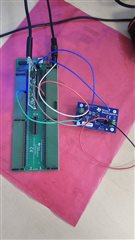

We are using LIN transceiver (TLIN2029EVM) to established the communication between the TMDSHSECDOCK control CARD Docking Station [Rev F] with C2000 F280015x control CARD and the LIN master (we are using Canoe interface for LIN master).

We have connected the LIN transceiver RX pin to TMDSHSECDOCK control CARD Docking Station [Rev F] RX pin i.e. PIN No.90(GPIO35) on Docking Station and Tx PIN NO.85(GPIO32) and LIN transceiver EN PIN NO.88(GPIO37).

Please find below LIN initialization api pseudo code description to configure LIN in a slave mode. 

void LINDrv_Init(void)
{
	/* Initialize LIN state to IDLE. */
	g_LIN_State = LIN_STATE_IDLE;
	
	/* Enable LIN peripheral Module Clock */
	SysCtl_enablePeripheral(SYSCTL_PERIPH_CLK_LINA);

    EALLOW;

    /* Set the Interrupt Handler */
    Interrupt_register(INT_LINA_0, &LINDrv_IntLevel0Handle);

    /* LIN Tx GPIO Configuration */
    GPIO_setPinConfig(GPIO_32_LINA_TX);
	
    /* Set the direction */
    GPIO_setDirectionMode(LIN_TX_GPIO_PIN,GPIO_DIR_MODE_OUT);

    /* Configure the Pin as PushPull */
    GPIO_setPadConfig(LIN_TX_GPIO_PIN,GPIO_PIN_TYPE_STD);

    /* LIN Rx GPIO Configuration */
    GPIO_setPinConfig(GPIO_35_LINA_RX);
    /* Set the direction */
    GPIO_setDirectionMode(LIN_RX_GPIO_PIN,GPIO_DIR_MODE_IN);

    /* Configure the Pin as PushPull */
    GPIO_setPadConfig(LIN_RX_GPIO_PIN,GPIO_PIN_TYPE_STD);

	/* Reset the Module */
	LIN_REG_SCIGCR0 |= LIN_SCIGCR0_RESET; 
	
	/* Reset the Software Reset Bit */
	LIN_REG_SCIGCR1 &= ~(LIN_SCIGCR1_SWNRST);
	
	/* Configure the LINRx and LINTx Pin */
	LIN_REG_SCIPIO0 |= (LIN_SCIPIO0_RXFUNC | LIN_SCIPIO0_TXFUNC);
	
    /* Select LIN Mode */
    LIN_REG_SCIGCR1 |= LIN_SCIGCR1_LINMODE;

	/* Configure the LIN Module in Slave mode */
	LIN_REG_SCIGCR1 |= (LIN_REG_SCIGCR1 & ~(LIN_SCIGCR1_CLK_MASTER));

	/* Disable the ID4/ID5 bits for length control*/
	LIN_REG_SCIGCR1 |= (LIN_REG_SCIGCR1 & ~(LIN_SCIGCR1_TIMINGMODE | LIN_SCIGCR1_COMMMODE));
	
	/* Debug mode */
	LIN_REG_SCIGCR1 |= (LIN_REG_SCIGCR1 & (~(LIN_SCIGCR1_CONT)));
	
	/* Configure the Parity */
	LIN_REG_SCIGCR1 |= LIN_SCIGCR1_PARITYENA;

    /* Configure the max Response Length */
    LIN_REG_SCIFORMAT |= ((((uint32_t)MAXLENGTH - (uint32_t)LIN_CONST_NO_ONE) << \
                                                    LIN_SCIFORMAT_LENGTH_S));

    /* Checksum Type Selection */
#if(LIN_CHECKSUM_TYPE == LIN_ENHANCEMENT_CHECKSUM_TYPE)
    {
        /* Configure the Enhancement type checksum */
        LIN_REG_SCIGCR1 |= LIN_SCIGCR1_CTYPE;
    }
#else
    {
        /* Configure the Classic type checksum */
        LIN_REG_SCIGCR1 |= (LIN_REG_SCIGCR1 & (~(LIN_SCIGCR1_CTYPE)));
    }
#endif
    /* Trigger Checksum Compare */
    LIN_REG_SCIGCR2 |= LIN_SCIGCR2_CC;

    /* Send CheckSum */
    LIN_REG_SCIGCR2 |= LIN_SCIGCR2_SC;

    /* Disable Auto BaudRate */
    LIN_REG_SCIGCR1 |= (LIN_REG_SCIGCR1 & (~LIN_SCIGCR1_ADAPT));

	/* Select Multi-buffer */
	LIN_REG_SCIGCR1 |= LIN_SCIGCR1_MBUFMODE;


	/* Disable LOOP-BACK Mode */
	LIN_REG_SCIGCR1 |= (LIN_REG_SCIGCR1 &~(LIN_SCIGCR1_LOOPBACK));

	/* Disable External Loop back mode */
	LIN_REG_IODFTCTRL &= ~(LIN_IODFTCTRL_IODFTENA_M |LIN_IODFTCTRL_LPBENA |
	                       LIN_IODFTCTRL_RXPENA);

	/* Synch break and synch delimiter additional bits */
	LIN_REG_COMP |= (LIN_SYNCH_BREAK_LEN | ((LIN_SYNCH_DELIMITER_LEN - 1U) << LIN_COMP_SDEL_S));

	/* Configure the BaudRate */
	LINDrv_SetBuadRate();

	/* Configure message filtering */
#if(LIN_HGENCTRL_TYPE == LIN_CONST_NO_ONE)
    {
	    /* Configure the Slave ID for message filtering */
	    LIN_REG_SCIGCR1 |= LIN_SCIGCR1_HGENCTRL;

	    /* Configure the Filter Compare Slave task ID byte*/
	    LIN_REG_ID |= (uint32_t)LIN_SLAVETASKIDBYTE << LIN_CONST_NO_EIGHT;

	    /* Configure the Rx Filter Mask */
	    LIN_REG_MASK |= ((uint32_t)LIN_RXMESSAGEID_FILTERMASK << LIN_CONST_NO_SIXTEEN);

	    /* Configure the Tx Filter Mask */
	    LIN_REG_MASK |= (uint32_t)LIN_TXMESSAGEID_FILTERMASK;
    }
#else
    {
        /* Configure the ID for message filtering */
        LIN_REG_SCIGCR1 |= (LIN_REG_SCIGCR1 & (~(LIN_SCIGCR1_HGENCTRL)));

        /* Configure the Filter Compare ID byte*/
        LIN_REG_ID |= (uint32_t)LIN_SLAVETASKIDBYTE;

        /* Configure the Rx Filter Mask */
        LIN_REG_MASK |= ((uint32_t)LIN_RXMSGID_FILTERMSK_ZERO << LIN_CONST_NO_SIXTEEN);

        /* Configure the Tx Filter Mask */
        LIN_REG_MASK |= (uint32_t)LIN_TXMSGID_FILTERMSK_ZERO;
    }
#endif

	/* Enable the Transmit */
	LIN_REG_SCIGCR1 |= LIN_SCIGCR1_TXENA;
	
	/* Enable the Receive */
	LIN_REG_SCIGCR1 |= LIN_SCIGCR1_RXENA;
	
    /* Reset the Software Reset Bit */
    LIN_REG_SCIGCR1 |= (LIN_SCIGCR1_SWNRST);

    EDIS;

	/* Enable Interrupt - Bit Error Interrupt, Physical Bus Error interrupt,
	 *                    Checksum Error Interrupt,  Sync Frame Error Interrupt,
	 *                    No Response Error Interrupt, Frame Error Interrupt,
	 *                    Over run Interrupt,  Parity Error Interrupt,
	                      ID Interrupt ,Timeout after Wake-up Signal Interrupt,
	                      Timeout after Three Wake-up Signal Interrupt  */
	LIN_REG_SCISETINT = ( LIN_SCISETINT_SETBEINT | LIN_SCISETINT_SETPBEINT | \
	                       LIN_SCISETINT_SETCEINT | LIN_SCISETINT_SETISFEINT | \
	                       LIN_SCISETINT_SETNREINT | LIN_SCISETINT_SETFEINT | \
	                       LIN_SCISETINT_SETOEINT | LIN_SCISETINT_SETPEINT | \
	                       LIN_SCISETINT_SETIDINT | LIN_SCISETINT_SETTIMEOUTINT |
	                       LIN_SCISETINT_SETTOA3WUSINT | LIN_SCISETINT_SETTOAWUSINT);

	/* Set Interrupt Level 0 */
	 LIN_REG_SCICLEARINTLVL = ( LIN_SCISETINT_SETBEINT | LIN_SCISETINT_SETPBEINT | \
                             LIN_SCISETINT_SETCEINT | LIN_SCISETINT_SETISFEINT | \
                             LIN_SCISETINT_SETNREINT | LIN_SCISETINT_SETFEINT | \
                             LIN_SCISETINT_SETOEINT | LIN_SCISETINT_SETPEINT | \
                             LIN_SCISETINT_SETIDINT | LIN_SCISETINT_SETTIMEOUTINT |
                             LIN_SCISETINT_SETTOA3WUSINT | LIN_SCISETINT_SETTOAWUSINT);

    /* Enable Global Interrupt */
    LIN_REG_GLB_INT_EN |= LIN_GLB_INT_EN_GLBINT0_EN << LIN_LINE0_INTERRUPT;

    /* Clear the Global Interrupt Status */
    LIN_REG_GLB_INT_FLG |= LIN_GLB_INT_CLR_INT0_FLG_CLR << LIN_LINE0_INTERRUPT;

    /* Enable Interrupts */
    Interrupt_enable(INT_LINA_0);

    /* No Error */
    g_LIN_ErrVal = LIN_NOERR;
}

Please let us know if we need to change any configuration pins on Docking station or control card.

Thanks in advance.

Regards,

Dinesh Reddy

  • Hi Dinesh,

    Here are some things to check/try:

    1. Just to make sure, are you calling EINT; to enable interrupts globally somewhere else in your code? This needs to be included in order for any interrupt to work.

    2. Try without slave mode and without being connected to any other device. Just see if the TX pin can transmit the message header as a master. If you see the header field when scoping the TX pin, then at least the LIN module chosen is configured correctly and hardware output is good.

    3. Next see if the RX pin of the device is receiving valid data from the master by taking a scope capture of the RX pin of the C2000 device when it is receiving data. Please make sure we can determine the width of a bit from the data using the capture, in order to make sure the baud rate is correct.

    Best Regards,

    Delaney

  • Hi Delaney,

    Thanks for Replying, please find below points that we tried as per your advice,

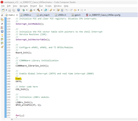
    1. yes, EINT has already been enabled in our workspace, please find below image for your reference.

    2. We tried LIN as master mode and Transmitting data to Tx Pin, still there is no data in TX Pin (verified with logic analyzer).

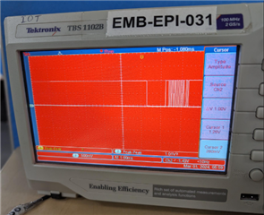
    3. We checked with Oscilloscope and observed 1V, please find below image for your reference.

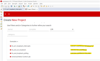
    NOTE: we tried using LIN examples, still there is no data in Tx and Rx PINs

    could you please let us know the exact configuration of LIN Tx and Rx pins from code composer "SysCfg" and "TMDSHSECDOCK (F2800157SPN_Schematic)"

  • Hi Dinesh,

    The below Control Card docking station pins should be used for the physical connections of the transceiver to the docking station.

    LINA_RX = GPIO35 = TMDSHSECDOCK pin 90 

    LINA_TX = GPIO37 = TMDSHSECDOCK pin 88

    The Sysconfig selections should be the following:

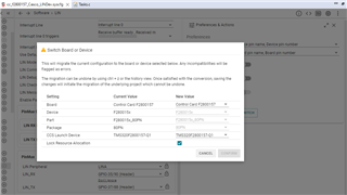
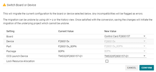
    In order to view the header pins for the docking station (labeled (Header)) in CSS Sysconfig, click the three dots in the upper right corner [More Views] >> Preferences and Actions >> Switch >> Board and select the board being used from the dropdown.

    Best Regards,

    Delaney

  • Hi Delaney,

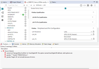
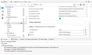
    We have tried peripheral and pin configuration in Sysconfig as per your suggestion, while configuring we are getting following error.

    This is how we selected Switch Board settings, please find below snapshot for your reference, let me know if it corrects or not.

    Thanks,

    Dinesh Reddy.

  • Hi Dinesh,

    Can you try this:

    1. Open the .syscfg file as text (right click on the .syscfg file >> Open With >> Generic Text Editor)

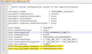
    2. Remove all $assign lines like the below.

    3. Save and close the Sysconfig text file and close the Sysconfig GUI.

    4. Reopen the Sysconfig GUI and try selecting the pins again.

    If this doesn't fix the issue, please share your Sysconfig text file and I can take a look.

    Best Regards,

    Delaney

  • Hi Delaney,

    We tried as per your advice still getting the same error.

    NOTE: I am unable to upload the SysCfg file in this thread. please let us know an alternative for sending file.

    Thanks,

    Dinesh Reddy

  • Hi Dinesh,

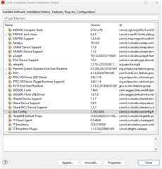
    What installation version of Sysconfig are you using?

    Best Regards,

    Delaney

  • Hi Delaney,

    we have installed Version 1.19.0.3426, Please find the below snapshot for your reference.

    Thanks,

    Dinesh Reddy.

  • Hi Dinesh,

    I was able to replicate the issue using the same Sysconfig version and configurations in CCS. There appears to be an issue with the code generated by Sysconfig when the board is selected. I will consult other experts to understand why this is happening and see if it's something that needs to be fixed on our end.

    However, different code is generated when there is no board selected (shown below) and should not cause the same build error. Can you try configuring Sysconfig with GPIO35 and GPIO37 without the F280015 Control Card selected and see if you receive the same build error? The docking station pins 90 and 88 will work regardless, they just won't show up in the GUI.

    Best Regards,

    Delaney

  • Hi Dinesh,

    After speaking with other experts, I believe I have found the cause. When adding the board to Sysconfig you need to uncheck "Lock Resource Allocation" to avoid these build errors.

    Let me know if this fixes the issue for you or if you have any more questions.

    Best Regards,

    Delaney

  • SysCfgFile.txt
    /**
     * These arguments were used when this file was generated. They will be automatically applied on subsequent loads
     * via the GUI or CLI. Run CLI with '--help' for additional information on how to override these arguments.
     * @cliArgs --board "/boards/TMDSCNCD2800157" --context "system" --product "C2000WARE@5.01.00.00"
     * @versions {"tool":"1.19.0+3426"}
     */
    
    /**
     * Import the modules used in this configuration.
     */
    const cputimer  = scripting.addModule("/driverlib/cputimer.js", {}, false);
    const cputimer1 = cputimer.addInstance();
    const lin       = scripting.addModule("/driverlib/lin.js", {}, false);
    const lin1      = lin.addInstance();
    
    /**
     * Write custom configuration values to the imported modules.
     */
    cputimer1.$name                    = "CPUTIMER0_1msTick";
    cputimer1.timerPeriod              = 120000;
    cputimer1.registerInterrupts       = true;
    cputimer1.startTimer               = true;
    cputimer1.enableInterrupt          = true;
    cputimer1.timerInt.enableInterrupt = true;
    
    lin1.$name                  = "myLIN0";
    lin1.enableInterrupt        = true;
    lin1.interruptFlags         = [" LIN_INT_ID"," LIN_INT_RX"];
    lin1.interruptLine          = ["LIN_INTERRUPT_LINE0"];
    lin1.interruptPriorityLine0 = [" LIN_INT_ID"," LIN_INT_RX"];
    lin1.useDefaultLin          = false;
    lin1.linMode                = "LIN_MODE_LIN_RESPONDER";
    lin1.lin.$assign            = "LINA";
    lin1.lin.lin_rxPin.$assign  = "hsecDigital.90";
    lin1.lin.lin_txPin.$assign  = "hsecDigital.88";
    

    Hi Delaney,

    Disabling "Lock Resource Allocation" didn't resolve the errors. I've attached the SysCfg file and a screen recording showing the attempt to uncheck it in the "lin_ex1_loopback_interrupts" workspace for your reference.

    Thanks,

    Dinesh Reddy.

  • Hi Dinesh,

    I'm sorry that didn't fix the issue. Can you try doing the steps in this thread to remove the current device from the project properties, and then try adding the board? If an old device is still set in the project properties, it could be overwriting the board setup in Sysconfig. This could be the reason you are seeing the build error.

    Best Regards,

    Delaney