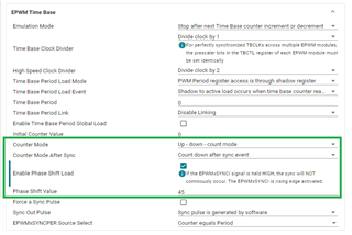
Hi
i am using TMS320F28377D Microcontroller
1. My requirement is generate a PWM wave (done by using EPWM1 and EPWM2 an given below code),
2. my requirement is to change duty cycle of PWM based on change potentiometer of ADC ( kindly provide which ADC pin can i use?)
which APIs can change phase shift of PWM wave.
Thanks,
Venkata Naresh
#include "driverlib.h"
#include "device.h"
//
// Defines
//
#define EPWM1_TIMER_TBPRD 2000U
#define EPWM1_MAX_CMPA 1000U
#define EPWM1_MIN_CMPA 1000U
#define EPWM1_MAX_CMPB 1950U
#define EPWM1_MIN_CMPB 50U
#define EPWM2_TIMER_TBPRD 2000U
#define EPWM2_MAX_CMPA 1800U
#define EPWM2_MIN_CMPA 200U
#define EPWM2_MAX_CMPB 1900U
#define EPWM2_MIN_CMPB 100U
#define EPWM3_TIMER_TBPRD 2000U
#define EPWM3_MAX_CMPA 500U
#define EPWM3_MIN_CMPA 1500U
#define EPWM3_MAX_CMPB 1200U
#define EPWM3_MIN_CMPB 800U
#define EPWM_CMP_UP 1U
#define EPWM_CMP_DOWN 0U
//
// Globals
//
typedef struct
{
uint32_t epwmModule;
uint16_t epwmCompADirection;
uint16_t epwmCompBDirection;
uint16_t epwmTimerIntCount;
uint16_t epwmMaxCompA;
uint16_t epwmMinCompA;
uint16_t epwmMaxCompB;
uint16_t epwmMinCompB;
}epwmInformation;
uint16_t adcAResult0;
uint16_t adcAResult1;
uint16_t adcBResult0;
uint16_t adcBResult1;
//
// Globals to hold the ePWM information used in this example
//
epwmInformation epwm1Info;
epwmInformation epwm2Info;
epwmInformation epwm3Info;
//
// Function Prototypes
//
void initEPWM1(void);
void initEPWM2(void);
void initEPWM3(void);
//
// Main
//
void main(void)
{
//
// Initialize device clock and peripherals
//
Device_init();
//
// Disable pin locks and enable internal pull ups.
//
Device_initGPIO();
//
// Initialize PIE and clear PIE registers. Disables CPU interrupts.
//
Interrupt_initModule();
//
// Initialize the PIE vector table with pointers to the shell Interrupt
// Service Routines (ISR).
//
Interrupt_initVectorTable();
//
// Configure GPIO0/1 , GPIO2/3 and GPIO4/5 as ePWM1A/1B, ePWM2A/2B and
// ePWM3A/3B pins respectively
//
GPIO_setPadConfig(0, GPIO_PIN_TYPE_STD);
GPIO_setPinConfig(GPIO_0_EPWM1A);
GPIO_setPadConfig(1, GPIO_PIN_TYPE_STD);
GPIO_setPinConfig(GPIO_1_EPWM1B);
GPIO_setPadConfig(2, GPIO_PIN_TYPE_STD);
GPIO_setPinConfig(GPIO_2_EPWM2A);
GPIO_setPadConfig(3, GPIO_PIN_TYPE_STD);
GPIO_setPinConfig(GPIO_3_EPWM2B);
GPIO_setPadConfig(4, GPIO_PIN_TYPE_STD);
GPIO_setPinConfig(GPIO_4_EPWM3A);
GPIO_setPadConfig(5, GPIO_PIN_TYPE_STD);
GPIO_setPinConfig(GPIO_5_EPWM3B);
GPIO_setPadConfig(8, GPIO_PIN_TYPE_STD);
GPIO_setPinConfig(GPIO_8_ADCSOCAO);
GPIO_setPadConfig(10, GPIO_PIN_TYPE_STD);
GPIO_setPinConfig(GPIO_10_ADCSOCBO);
//
// Disable sync(Freeze clock to PWM as well)
//
SysCtl_disablePeripheral(SYSCTL_PERIPH_CLK_TBCLKSYNC);
//
// Enable sync and clock to PWM
//
SysCtl_enablePeripheral(SYSCTL_PERIPH_CLK_TBCLKSYNC);
//
// Enable Global Interrupt (INTM) and realtime interrupt (DBGM)
//
EINT;
ERTM;
//
// IDLE loop. Just sit and loop forever (optional):
//
for(;;)
{
ADC_forceSOC(ADCC_BASE, ADC_SOC_NUMBER2);
ADC_forceSOC(ADCC_BASE, ADC_SOC_NUMBER3);
ADC_forceSOC(ADCB_BASE, ADC_SOC_NUMBER2);
ADC_forceSOC(ADCB_BASE, ADC_SOC_NUMBER3);
adcAResult0 = ADC_readResult(ADCCRESULT_BASE, ADC_SOC_NUMBER2);
adcAResult1 = ADC_readResult(ADCCRESULT_BASE, ADC_SOC_NUMBER3);
adcBResult0 = ADC_readResult(ADCBRESULT_BASE, ADC_SOC_NUMBER2);
adcBResult1 = ADC_readResult(ADCBRESULT_BASE, ADC_SOC_NUMBER3);
// Duty_1=(2000/4096)*adcAResult0;
// Duty_2=(2000/4096)*adcAResult1;
// Duty_3=(2000/4096)*adcBResult0;
// Duty_4=(2000/4096)*adcBResult1;
DEVICE_DELAY_US(10000000);
initEPWM1();
initEPWM2();
initEPWM3();
}
}
//
// initEPWM1 - Configure ePWM1
//
void initEPWM1()
{
//
// Set-up TBCLK
//
EPWM_setTimeBasePeriod(EPWM1_BASE, EPWM1_TIMER_TBPRD);
EPWM_setPhaseShift(EPWM1_BASE, 0U);
EPWM_setTimeBaseCounter(EPWM1_BASE, 0U);
//
// Set Compare values
//
EPWM_setCounterCompareValue(EPWM1_BASE,
EPWM_COUNTER_COMPARE_A,
adcAResult0);
EPWM_setCounterCompareValue(EPWM1_BASE,
EPWM_COUNTER_COMPARE_B,
adcAResult1);
//
// Set up counter mode
//
EPWM_setTimeBaseCounterMode(EPWM1_BASE, EPWM_COUNTER_MODE_UP_DOWN);
EPWM_disablePhaseShiftLoad(EPWM1_BASE);
EPWM_setClockPrescaler(EPWM1_BASE,
EPWM_CLOCK_DIVIDER_1,
EPWM_HSCLOCK_DIVIDER_1);
//
// Set up shadowing
//
EPWM_setCounterCompareShadowLoadMode(EPWM1_BASE,
EPWM_COUNTER_COMPARE_A,
EPWM_COMP_LOAD_ON_CNTR_ZERO);
EPWM_setCounterCompareShadowLoadMode(EPWM1_BASE,
EPWM_COUNTER_COMPARE_B,
EPWM_COMP_LOAD_ON_CNTR_ZERO);
//
// Set actions
//
EPWM_setActionQualifierAction(EPWM1_BASE,
EPWM_AQ_OUTPUT_A,
EPWM_AQ_OUTPUT_LOW,
EPWM_AQ_OUTPUT_ON_TIMEBASE_UP_CMPA);
EPWM_setActionQualifierAction(EPWM1_BASE,
EPWM_AQ_OUTPUT_A,
EPWM_AQ_OUTPUT_HIGH,
EPWM_AQ_OUTPUT_ON_TIMEBASE_DOWN_CMPA);
EPWM_setActionQualifierAction(EPWM1_BASE,
EPWM_AQ_OUTPUT_B,
EPWM_AQ_OUTPUT_HIGH,
EPWM_AQ_OUTPUT_ON_TIMEBASE_UP_CMPB);
EPWM_setActionQualifierAction(EPWM1_BASE,
EPWM_AQ_OUTPUT_B,
EPWM_AQ_OUTPUT_LOW,
EPWM_AQ_OUTPUT_ON_TIMEBASE_DOWN_CMPB);
//
// Interrupt where we will change the Compare Values
// Select INT on Time base counter zero event,
// Enable INT, generate INT on 3rd event
//
EPWM_setInterruptSource(EPWM1_BASE, EPWM_INT_TBCTR_ZERO);
EPWM_enableInterrupt(EPWM1_BASE);
EPWM_setInterruptEventCount(EPWM1_BASE, 3U);
}
//
// initEPWM2 - Configure ePWM2
//
void initEPWM2()
{
//
// Set-up TBCLK
//
EPWM_setTimeBasePeriod(EPWM2_BASE, EPWM2_TIMER_TBPRD);
EPWM_setPhaseShift(EPWM2_BASE, 0U);
EPWM_setTimeBaseCounter(EPWM2_BASE, 0U);
//
// Set Compare values
//
EPWM_setCounterCompareValue(EPWM2_BASE,
EPWM_COUNTER_COMPARE_A,
adcBResult0);
EPWM_setCounterCompareValue(EPWM2_BASE,
EPWM_COUNTER_COMPARE_B,
adcBResult1);
//
// Set-up counter mode
//
EPWM_setTimeBaseCounterMode(EPWM2_BASE, EPWM_COUNTER_MODE_UP_DOWN);
EPWM_disablePhaseShiftLoad(EPWM2_BASE);
EPWM_setClockPrescaler(EPWM2_BASE,
EPWM_CLOCK_DIVIDER_1,
EPWM_HSCLOCK_DIVIDER_1);
//
// Set-up shadowing
//
EPWM_setCounterCompareShadowLoadMode(EPWM2_BASE,
EPWM_COUNTER_COMPARE_A,
EPWM_COMP_LOAD_ON_CNTR_ZERO);
EPWM_setCounterCompareShadowLoadMode(EPWM2_BASE,
EPWM_COUNTER_COMPARE_B,
EPWM_COMP_LOAD_ON_CNTR_ZERO);
//
// Set Action qualifier
EPWM_setActionQualifierAction(EPWM2_BASE,
EPWM_AQ_OUTPUT_A,
EPWM_AQ_OUTPUT_LOW,
EPWM_AQ_OUTPUT_ON_TIMEBASE_UP_CMPA);
EPWM_setActionQualifierAction(EPWM2_BASE,
EPWM_AQ_OUTPUT_A,
EPWM_AQ_OUTPUT_HIGH,
EPWM_AQ_OUTPUT_ON_TIMEBASE_DOWN_CMPA);
EPWM_setActionQualifierAction(EPWM2_BASE,
EPWM_AQ_OUTPUT_B,
EPWM_AQ_OUTPUT_HIGH,
EPWM_AQ_OUTPUT_ON_TIMEBASE_UP_CMPB);
EPWM_setActionQualifierAction(EPWM2_BASE,
EPWM_AQ_OUTPUT_B,
EPWM_AQ_OUTPUT_LOW,
EPWM_AQ_OUTPUT_ON_TIMEBASE_DOWN_CMPB);
//
// Interrupt where we will change the Compare Values
// Select INT on Time base counter zero event,
// Enable INT, generate INT on 3rd event
//
EPWM_setInterruptSource(EPWM2_BASE, EPWM_INT_TBCTR_ZERO);
EPWM_enableInterrupt(EPWM2_BASE);
EPWM_setInterruptEventCount(EPWM2_BASE, 3U);
}
//
// initEPWM3 - Configure ePWM3
//
void initEPWM3(void)
{
//
// Set-up TBCLK
//
EPWM_setTimeBaseCounterMode(EPWM3_BASE, EPWM_COUNTER_MODE_UP_DOWN);
EPWM_setTimeBasePeriod(EPWM3_BASE, EPWM3_TIMER_TBPRD);
EPWM_disablePhaseShiftLoad(EPWM3_BASE);
EPWM_setPhaseShift(EPWM3_BASE, 0U);
EPWM_setTimeBaseCounter(EPWM3_BASE, 0U);
EPWM_setClockPrescaler(EPWM3_BASE,
EPWM_CLOCK_DIVIDER_1,
EPWM_HSCLOCK_DIVIDER_1);
//
// Set up shadowing
//
EPWM_setCounterCompareShadowLoadMode(EPWM3_BASE,
EPWM_COUNTER_COMPARE_A,
EPWM_COMP_LOAD_ON_CNTR_ZERO);
EPWM_setCounterCompareShadowLoadMode(EPWM3_BASE,
EPWM_COUNTER_COMPARE_B,
EPWM_COMP_LOAD_ON_CNTR_ZERO);
//
// Set Compare values
//
EPWM_setCounterCompareValue(EPWM3_BASE,
EPWM_COUNTER_COMPARE_A,
EPWM3_MIN_CMPA);
EPWM_setCounterCompareValue(EPWM3_BASE,
EPWM_COUNTER_COMPARE_B,
EPWM3_MAX_CMPB);
//
// Set actions
//
EPWM_setActionQualifierAction(EPWM3_BASE,
EPWM_AQ_OUTPUT_A,
EPWM_AQ_OUTPUT_LOW,
EPWM_AQ_OUTPUT_ON_TIMEBASE_UP_CMPA);
EPWM_setActionQualifierAction(EPWM3_BASE,
EPWM_AQ_OUTPUT_A,
EPWM_AQ_OUTPUT_HIGH,
EPWM_AQ_OUTPUT_ON_TIMEBASE_DOWN_CMPA);
EPWM_setActionQualifierAction(EPWM3_BASE,
EPWM_AQ_OUTPUT_B,
EPWM_AQ_OUTPUT_HIGH,
EPWM_AQ_OUTPUT_ON_TIMEBASE_UP_CMPB);
EPWM_setActionQualifierAction(EPWM3_BASE,
EPWM_AQ_OUTPUT_B,
EPWM_AQ_OUTPUT_LOW,
EPWM_AQ_OUTPUT_ON_TIMEBASE_DOWN_CMPB);
//
// Interrupt where we will change the Compare Values
// Select INT on Time base counter zero event,
// Enable INT, generate INT on 3rd event
//
EPWM_setInterruptSource(EPWM3_BASE, EPWM_INT_TBCTR_ZERO);
EPWM_enableInterrupt(EPWM3_BASE);
EPWM_setInterruptEventCount(EPWM3_BASE, 3U);
}


