This thread has been locked.

If you have a related question, please click the "Ask a related question" button in the top right corner. The newly created question will be automatically linked to this question.

TMS320F28P650DK: How to use GPI/GPO of EtherCAT

Part Number: TMS320F28P650DK

Hi Team,

According to the TRM description, some of the GPI or GPO functions of EtherCAT are routed to two pads. The customer tested GPI3. GPI3 is connected to GPIO3 and GPIO103 respectively. But why does this register have no effect on which set of PAD is used, whether it is configured or not?
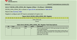
Regardless of whether this register is configured or not, this function can be used only after configuring the GPIO pinmux. Customers think this is unreasonable.

And could you please explain the general process of using the GPI/GPO function?

--

Thanks & Regards

  • Hi Yale,

    Regardless of whether this register is configured or not, this function can be used only after configuring the GPIO pinmux. Customers think this is unreasonable.

    We need the GPIO pinmux to allow multiple functionalities to be brought out to the pins. We wouldn't want to internally connect multiple digital outputs to the same pin, since that could end up with one trying to drive low while the other tries to drive low. That would be a bug problem!

    And could you please explain the general process of using the GPI/GPO function?

    We do have this section in the TRM:


    Best Regards,

    Ben Collier