This thread has been locked.

If you have a related question, please click the "Ask a related question" button in the top right corner. The newly created question will be automatically linked to this question.

TMS320F28377D: Unstabled SDRAM data when use EMIF

Part Number: TMS320F28377D
Other Parts Discussed in Thread: SN54LVTH16245A

Hi Team,

The system architecture is as follows:

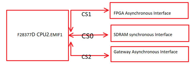
During the test, it was found that if the asynchronous device gateway is mounted, the data in the synchronous device SDRAM is unstable, as shown in the figure below. Unplug the gateway and the SDRAM data will be stable.

Use an oscilloscope to test the chip and select CS0 (SDRAM) and CS2 (gateway), as shown below:

What are the possible reasons for unstable SDRAM data?

Best Regards,

Zane

  • Hello Zane,

    Please refer to the Design and Usage Guidelines for the C2000 EMIF, this application report goes over the necessary information for proper EMIF usage in applications/hardware.

  • Hi Omer,

    There is a very strange phenomenon. When the gateway chip select signal is not enabled(High), as long as the gateway device is plugged in, the SDRAM data will be abnormal. What could be the reason for this?

    Best Regards,

    Zane

  • Hi Zane,

    When the gateway chip select signal is not enabled(High), as long as the gateway device is plugged in, the SDRAM data will be abnormal.

    Can you please elaborate on this? What do you mean by abnormal? Is it the values on the bus connection which is abnormal or the actual values in the SDRAM?

  • Hi Omer,

    The abnormal is mean that when use CSS to view the variables. Some variables will change, you can see the yellow data, those date store in SDRAM which memory map to 0x8000 0000-0x8FFF FFFF. In fact, those variables should not be change while the program running.

    Best Regards,

    Zane

  • Hello Zane,

    If you try to use a variable to store some of the values in the SDRAM locally (i.e. not at an address that the EMIF would need to be used), do you get the same issue? I've not used CCS to monitor memory that's stored externally via the connected device, so I'm not sure how well it would do this.

  • Hi Omer,

    From the describe "EMIF keeps this SDRAM chip select active"

    I think the chip select of 0&2 should look like below, CS0 will delay CS2, is right? 

    If I am right, the customer's chip select signal is wrong.

    Best Regards,

    Zane

  • Hello Zane,

    Yes, when accessing asynchronous memory the chip select should go high for the SDRAM (disabled) and will be low otherwise. What was the customer's confusion in the scope screenshot they have? It looks to be working as expected, were they expecting/needing some delay between when CS0 goes high and CS2 goes low?

  • Hi Omer,

    CS0 goes High, then CS2 goes low, is the right timing order?

    Best Regards,

    Zane

  • Hello Zane,

    That appears to be the case, I can't find documentation to cite for you on the exact timing but based on what the customer has seen and how the behavior is described, yes this is the timing order.

  • Hi Omer

    Now we can basically confirm that by plugging in the gateway board, the data of SDRAM will be affected, without inserting SDRAM and fpga will work properly
    Considering that the gateway board is a separate single board and that the bus routing path is long.

    So adding a bus driver chip such as the SN54LVTH16245A to the gateway board can solve this problem?

    Do you have other way to solve this problem?

    Thanks for your help!

    Best Regards,

    Zane

  • Hello Zane,

    Can you clarify what you mean by the SDRAM is not working when the gateway board plugged in? Is it returning invalid data, not responding, or doing something else? Is the customer trying to use the SDRAM and gateway simultaneously? What is this gateway actually doing, is it routing something to the SDRAM and that's why they need to work together?

    Please keep in mind I'm not familiar with what a gateway board is or what the intention is in using it, providing me this context will better equip me to help you and the customer.

  • Hi Omer,

    Thanks for your patience!

    When plugged in Gateway device, it will return invalid data.

    Customer want to use them simultaneously, F282377D will get some data from Gateway device.

    All the three devices are on EMIF1 interface. Inevitably, there will be mutiplexing of address lines and data lines.

    Best Regards,

    Zane

  • Hello Zane,

    When plugged in Gateway device, it will return invalid data.

    Please define invalid in this case, is it all 0's, all F's, random values, the correct value shifted by some number of bits, etc.?

    Customer want to use them simultaneously, F282377D will get some data from Gateway device.

    All the three devices are on EMIF1 interface. Inevitably, there will be mutiplexing of address lines and data lines.

    I'm assuming they don't mean literally simultaneously (i.e. trying to read/write to the SDRAM and gateway device at the exact same time), EMIF1 has only one set of address lines. The multiplexing should be happening using the chip select (CSn) since this is connected to the appropriate device being accessed with the EMIF.

    Can you or the customer please provide a detailed schematic of what the connections are between the EMIF and each of the 3 devices being connected? I need to see address lines, data lines, chip selects, enables, etc. to get a full understanding of the setup. If there are anything besides just wires in the connection of any of these lines, please also highlight those.

  • Invalid means that the data should not have changed, but it has changed

  • Hi Omer,

    I have sent you the schematic a fewer days ago. I will resend them to you! Your help will be very important for customer!

    Best Regards

    Zane

  • Hello Zane,

    As you have already emailed the schematic review mailing list, let me know if they respond with an answer. The files you attached are not ones I can open, I was more asking for an actual image that laid out the circuit diagram connections.

    I did talk with another expert, they mentioned that the bus driver chip would help with not having any loading present to the F2837xD's EMIF pins.

    Invalid means that the data should not have changed, but it has changed

    So accessing the same address results in two different values being read? Are these reads adjacent or are they between other operations the EMIF is doing for the other devices connected to it?