This thread has been locked.

If you have a related question, please click the "Ask a related question" button in the top right corner. The newly created question will be automatically linked to this question.

TMS320F28075: MCU Configured as slave, receiving corrupt data when other buses are transferring data.

Part Number: TMS320F28075
Other Parts Discussed in Thread: C2000WARE

I have the TMS320F28075 configured as a slave, on a SPI bus with two other devices. If only the TMS320 is selected and transferring data, everything works great. However, when other devices on the SPI bus are selected, the data on the TMS320 is sometimes corrupt. The key word here is sometimes, because the data isn't always corrupt.

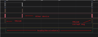
Here is a logic capture of what happens:

There are 3 messages sent here. First, TMS320 is selected and that transfer is successful. Then, another device on the bus is selected, that transfer is good too. Then the 3rd transfer, the TMS320 is selected again. The TMS320 receives incorrect data here.

And here is that 3rd message zoomed in:

And here is what the data looks like when I debug (I should see: 0x01 0x01 0x00 0x00 0x00 0x00 0x00):

I know this isn't the best example, since most of the data sent here is 0x00. But I've tried with other messages that have more specific values, and I'll always receive the same thing as the above pic. Plus I have a CRC I use to validate the data, so it's easy to tell when it is incorrect.

This corrupt data only happens immediately after another device on the SPI bus has transferred. So I know it's related to that. If there are no other transfers on the SPI bus, I see no corrupt data. I've tested this by running for 30 minutes with no other devices. I saw no corrupt data. 

It's strange, because I have the TMS320 SPI configured to interrupt on the RX buffer being 1. When the other device on the bus transfers data, the TMS320 does not interrupt. So the RX buffer is not getting filled. However, the data is still corrupt. Also, the TMS320 never interferes with other devices' transfers.

Here is how I have my SPI configured on the TMS320:

void McuCommsInit(void)
{
    //
    // GPIO55 is the SPISOMIA.
    //
    GPIO_setMasterCore(55, GPIO_CORE_CPU1);
    GPIO_setPinConfig(GPIO_55_SPISOMIA);
    GPIO_setPadConfig(55, GPIO_PIN_TYPE_STD);
    GPIO_setQualificationMode(55, GPIO_QUAL_ASYNC);

    //
    // GPIO54 is the SPISIMOA clock pin.
    //
    GPIO_setMasterCore(54, GPIO_CORE_CPU1);
    GPIO_setPinConfig(GPIO_54_SPISIMOA);
    GPIO_setPadConfig(54, GPIO_PIN_TYPE_STD);
    GPIO_setQualificationMode(54, GPIO_QUAL_ASYNC);

    //
    // GPIO57 is the SPISTEA.
    //
    GPIO_setMasterCore(57, GPIO_CORE_CPU1);
    GPIO_setPinConfig(GPIO_57_SPISTEA);
    GPIO_setPadConfig(57, GPIO_PIN_TYPE_STD);
    GPIO_setQualificationMode(57, GPIO_QUAL_ASYNC);

    //
    // GPIO56 is the SPICLKA.
    //
    GPIO_setMasterCore(56, GPIO_CORE_CPU1);
    GPIO_setPinConfig(GPIO_56_SPICLKA);
    GPIO_setPadConfig(56, GPIO_PIN_TYPE_STD);
    GPIO_setQualificationMode(56, GPIO_QUAL_ASYNC);

    SPI_disableModule(SPIA_BASE);
    SPI_setConfig(SPIA_BASE, DEVICE_LSPCLK_FREQ, SPI_PROT_POL0PHA0,
        SPI_MODE_SLAVE, 2500000, 8);

    SPI_disableLoopback(SPIA_BASE);
    SPI_enableTalk(SPIA_BASE);
    SPI_enableFIFO(SPIA_BASE);

    SPI_resetTxFIFO(SPIA_BASE);
    SPI_resetRxFIFO(SPIA_BASE);

    SPI_enableModule(SPIA_BASE);

    SPI_enableInterrupt(SPIA_BASE, SPI_INT_RXFF);
    SPI_setFIFOInterruptLevel(SPIA_BASE, SPI_FIFO_TX16, SPI_FIFO_RX1);

    Interrupt_register(INT_SPIA_RX, &RxSpiInterrupt);
    Interrupt_enable(INT_SPIA_RX);

    GPIO_setInterruptPin(57, GPIO_INT_XINT1);
    GPIO_setInterruptType(GPIO_INT_XINT1, GPIO_INT_TYPE_BOTH_EDGES);
    GPIO_enableInterrupt(GPIO_INT_XINT1);

    Interrupt_register(INT_XINT1, &ChipSelectInterrupt);
    Interrupt_enable(INT_XINT1);
}

And here is how I am reading out SPI data:

void ReadSpiReceiveData(void)
{
    SPI_RxFIFOLevel rxFifoStat = SPI_getRxFIFOStatus(SPIA_BASE);
    uint8_t count = 0;

    while(rxFifoStat != SPI_FIFO_RXEMPTY)
    {
        count++;
        WriteToBuffer(SPI_readDataNonBlocking(SPIA_BASE));
        rxFifoStat = SPI_getRxFIFOStatus(SPIA_BASE);
    }

    SPI_resetRxFIFO(SPIA_BASE);
}

  • Hi Olive,

    Thanks for the detailed question. I have some initial follow up questions/suggestions:

    1. Are you referencing any of the software examples from C2000Ware already? If not, I'd suggest taking a look at driverlib example 3 for this device ({C2000Ware}\driverlib\f2807x\examples\cpu1\spi\spi_ex3_external_loopback_fifo_interrupts.c) and follow a similar SPI configuration sequence from there in terms of clearing the interrupt status and setting up interrupts before re-enabling SPI at the very end of the setup. (Also, are you clearing the interrupt flag and acknowledging the interrupt inside RX int?)
    2. Are you seeing the ReadSpiReceiveData() "count" increment properly?
    3. It may help to toggle a GPIO within your ReadSpiReceiveData() to help follow activity.
    4. To be clear, the code is not getting stuck in your "while loop", right?
    5. Could you perhaps explain a bit more of what you mean by "the RX buffer is not getting filled. However, the data is still corrupt"?
    6. One more thing to check is be sure that the clock modes of this device and of other devices are the same. They may be called something different depending on manufacturers, but they should be latching and transmitting data with the same scheme in regards to the SPI clock.

    Best Regards,

    Allison

  • Hi Allison,

    1. Okay, I've modified my code to more match theirs (there wasn't too many updates be honest):

    void McuCommsInit(void)
    {
        //
        // GPIO55 is the SPISOMIA.
        //
        GPIO_setMasterCore(55, GPIO_CORE_CPU1);
        GPIO_setPinConfig(GPIO_55_SPISOMIA);
        GPIO_setPadConfig(55, GPIO_PIN_TYPE_STD);
        GPIO_setQualificationMode(55, GPIO_QUAL_ASYNC);
    
        //
        // GPIO54 is the SPISIMOA clock pin.
        //
        GPIO_setMasterCore(54, GPIO_CORE_CPU1);
        GPIO_setPinConfig(GPIO_54_SPISIMOA);
        GPIO_setPadConfig(54, GPIO_PIN_TYPE_STD);
        GPIO_setQualificationMode(54, GPIO_QUAL_ASYNC);
    
        //
        // GPIO57 is the SPISTEA.
        //
        GPIO_setMasterCore(57, GPIO_CORE_CPU1);
        GPIO_setPinConfig(GPIO_57_SPISTEA);
        GPIO_setPadConfig(57, GPIO_PIN_TYPE_STD);
        GPIO_setQualificationMode(57, GPIO_QUAL_ASYNC);
    
        //
        // GPIO56 is the SPICLKA.
        //
        GPIO_setMasterCore(56, GPIO_CORE_CPU1);
        GPIO_setPinConfig(GPIO_56_SPICLKA);
        GPIO_setPadConfig(56, GPIO_PIN_TYPE_STD);
        GPIO_setQualificationMode(56, GPIO_QUAL_ASYNC);
    
        SPI_disableModule(SPIA_BASE);
        SPI_setConfig(SPIA_BASE, DEVICE_LSPCLK_FREQ, SPI_PROT_POL0PHA0,
            SPI_MODE_SLAVE, 2500000, 8);
    
        SPI_disableLoopback(SPIA_BASE);
        SPI_setEmulationMode(SPIA_BASE, SPI_EMULATION_FREE_RUN);
    
        SPI_enableTalk(SPIA_BASE);
        SPI_enableFIFO(SPIA_BASE);
    
        SPI_resetTxFIFO(SPIA_BASE);
        SPI_resetRxFIFO(SPIA_BASE);
    
        SPI_enableInterrupt(SPIA_BASE, SPI_INT_RXFF);
        SPI_clearInterruptStatus(SPIA_BASE, SPI_INT_RXFF);
        SPI_setFIFOInterruptLevel(SPIA_BASE, SPI_FIFO_TX16, SPI_FIFO_RX1);
    
        Interrupt_register(INT_SPIA_RX, &RxSpiInterrupt);
        Interrupt_enable(INT_SPIA_RX);
    
        GPIO_setInterruptPin(57, GPIO_INT_XINT1);
        GPIO_setInterruptType(GPIO_INT_XINT1, GPIO_INT_TYPE_BOTH_EDGES);
        GPIO_enableInterrupt(GPIO_INT_XINT1);
    
        Interrupt_register(INT_XINT1, &ChipSelectInterrupt);
        Interrupt_enable(INT_XINT1);
    
        SPI_enableModule(SPIA_BASE);
    }

    2. Whoops, forgot to remove the count variable, that was just for debug. But yes, the receive function works properly from all the debugging I've done. I will always get correct data if no other devices send on the SPI bus.

    3. I've done this, it looks like it is working correctly:

    4. Correct, it never gets stuck in the while loop.

    5. If I constantly check the RX buffer and toggle a GPIO when it is not empty, I never see the GPIO toggle after another device has sent a message on the bus. So the other device on the bus is not filling the RX buffer. It's like it's just corrupting the next read of the RX buffer, when there is legit data in there. The only way to clear the corrupt data is to receive a real message intended for the TMS320. Because of this behavior, it seems like something is happening on the hardware level of the SPI peripheral to me. I should note though, I've looked at the signals on my logic analyzer and everything looks good. The TMS320's chip select line is high when other devices are sending.

    6. The other devices just have a different clock speed, otherwise it is the same settings. I tried changing them to the same speed as the TMS320, just to see if that would make a difference, and it didn't seem to.

  • Hi Olive,

    Thanks for the updates. A few notes to make sure I'm aligned on the situation:

    • So if I'm understanding correctly, you have no issues communicating when the F2807x device is the only SPI slave. But when there are other devices communicating on the bus, the SPI of F2807x receives incorrect data after (but is the data that is transmitted from F2807x here correct still?)
    • My understanding is also that you are seeing a GPIO toggle once each time the RX interrupt occurs on F2807x (could you instead set the GPIO high at the beginning of the interrupt and low at the end so we can see the duration and verify the progression through?)

    And a few more questions:

    1. Is the issue consistent in that every time another device communicates in between transmissions with F2807x you see this received data issue? 
    2. If the RX interrupt is not being called after another device has sent a message on the line, do you still see data in the RXEMU register? If you set a breakpoint in your RX interrupt, does the program still hit it?
    3. Can I ask how you are reading the RX buffer? If you are looking at RXBUF directly in CCS this can actually clear the SPI INT FLAG bit, so you'll want to look at the RXEMU register instead.  
    4. Are the "other" devices on the bus also C2000 devices?
    5. Just to be clear, so the clock mode you are using should be transmitting data on the rising edge of the clock and latching received data on the falling edge of the SPI clock, correct?
    6. Are you using/clearing the TALK bit when not communication with F2807x device? 

    Sorry for all the questions, just trying to be sure I have a good understanding of the issue and symptoms Slight smile

    Best Regards,

    Allison