Other Parts Discussed in Thread: C2000WARE
I used the CAN simple transmit example code from C2000 . I am getting output when I tried the same code in EVALUATION BOARD LAUNCHXL-F29379D
But I have custom board which is TMS320F28377D. I am not getting any output when i tried to probe with Oscilloscope.
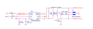
This is the transceiver circuit . I am using CAN B transmit .CAN_2_TX and CAN_2_RX are the pins coming from Controller.


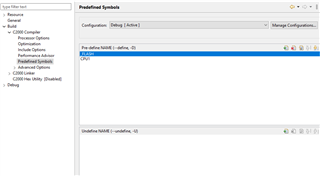
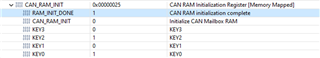
 ---> in main.c
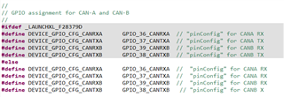
 --->in device.h
 ---> in pin_map.h