This thread has been locked.

If you have a related question, please click the "Ask a related question" button in the top right corner. The newly created question will be automatically linked to this question.

TMS320F28386S: Error due to change of EPWM pin

Expert 2590 points
Part Number: TMS320F28386S
Other Parts Discussed in Thread: SYSCONFIG

Hi All

A 2.5 MHz clock is generated on the PWM pin.
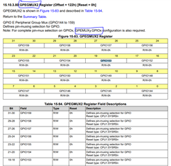
Before the design change, GPIO6/7 (ePWM4A/4B) could generate the clock without problems,
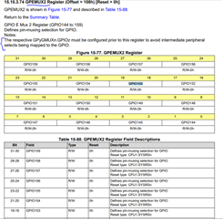
but when the pins were changed to GPIO167/168 (ePWM12A/12B), the output was not generated.
The pin settings are the same before and after the change.

1, Can all ePWM pins be used in the same way? Or are there functional restrictions depending on the pin?

2, If there are functional restrictions, is there any way to generate a 2.5MHz clock signal from GPIO167/168 (ePWM12A/12B)?

Best Regards,

Ito

  • Hi Ito,

    There is no limitation on usage of the GPIO pins. You should be able to use 167/168 for EPWM12A/B

    Can you share your GPIO settings configuration code ?

    Thanks,

    Prarthan.

  • Remember that for GPIO167/168 you need to configure GPIO F peripheral group mux


    Thanks!

  • Hi Bhatt,

    We will send you the customer's firmware and ask you to authenticate the Friendship.

    Best Regards

    Ito

  • Hi,

    Were you able to confirm the questions asked in my previous reply about the gpio peripheral group muxing config ?

    Thanks,

    Prarthan

  • Hi Bhatt,

    Yes, GPFGMUX1 register was set up.

    I send a configuration code file by private messege.

    Best Regards, 

    Ito

  • I am not able to see any gpio configurations in the file you shared.

    Please send me only the code related to gpio 167 and 168 pins configuration.

  • Hi Bhatt, 

    This is the code related to GPIO 167 and 168 pins configuration.

    #define GPIO_GPFQSEL1_GPIO167_S 14U
    #define GPIO_GPFQSEL1_GPIO167_M 0xC000U // Select input qualification type for GPIO167
    #define GPIO_GPFQSEL1_GPIO168_S 16U
    #define GPIO_GPFQSEL1_GPIO168_M 0x30000U // Select input qualification type for GPIO168

    #define GPIO_GPFMUX1_GPIO167_S 14U
    #define GPIO_GPFMUX1_GPIO167_M 0xC000U // Defines pin-muxing selection for GPIO167
    #define GPIO_GPFMUX1_GPIO168_S 16U
    #define GPIO_GPFMUX1_GPIO168_M 0x30000U // Defines pin-muxing selection for GPIO168

    #define GPIO_GPFDIR_GPIO167 0x80U // Defines direction for this pin in GPIO mode
    #define GPIO_GPFDIR_GPIO168 0x100U // Defines direction for this pin in GPIO mode

    #define GPIO_GPFPUD_GPIO167 0x80U // Pull-Up Disable control for this pin
    #define GPIO_GPFPUD_GPIO168 0x100U // Pull-Up Disable control for this pin

    #define GPIO_GPFINV_GPIO167 0x80U // Input inversion control for this pin
    #define GPIO_GPFINV_GPIO168 0x100U // Input inversion control for this pin

    #define GPIO_GPFODR_GPIO167 0x80U // Outpout Open-Drain control for this pin
    #define GPIO_GPFODR_GPIO168 0x100U // Outpout Open-Drain control for this pin

    #define GPIO_GPFGMUX1_GPIO167_S 14U
    #define GPIO_GPFGMUX1_GPIO167_M 0xC000U // Defines pin-muxing selection for GPIO167
    #define GPIO_GPFGMUX1_GPIO168_S 16U
    #define GPIO_GPFGMUX1_GPIO168_M 0x30000U // Defines pin-muxing selection for GPIO168

    #defineGPIO_GPFCSEL1_GPIO167_S 28U
    #define GPIO_GPFCSEL1_GPIO167_M 0xF0000000U // GPIO167 Master CPU Select
    #define GPIO_GPFCSEL2_GPIO168_S 0U
    #define GPIO_GPFCSEL2_GPIO168_M 0xFU // GPIO168 Master CPU Select

    #define GPIO_GPFLOCK_GPIO167 0x80U // Configuration Lock bit for this pin
    #define GPIO_GPFLOCK_GPIO168 0x100U // Configuration Lock bit for this pin

    #define GPIO_GPFCR_GPIO167 0x80U // Configuration lock commit bit for this pin
    #define GPIO_GPFCR_GPIO168 0x100U // Configuration lock commit bit for this pin

    #define GPIO_GPFDAT_GPIO167 0x80U // Data Register for this pin
    #define GPIO_GPFDAT_GPIO168 0x100U // Data Register for this pin

    #define GPIO_GPFSET_GPIO167 0x80U // Output Set bit for this pin
    #define GPIO_GPFSET_GPIO168 0x100U // Output Set bit for this pin

    #define GPIO_GPFCLEAR_GPIO167 0x80U // Output Clear bit for this pin
    #define GPIO_GPFCLEAR_GPIO168 0x100U // Output Clear bit for this pin

    #define GPIO_GPFTOGGLE_GPIO167 0x80U // Output Toggle bit for this pin
    #define GPIO_GPFTOGGLE_GPIO168 0x100U // Output Toggle bit for this pin

    Best Regards,

    Ito

  • Hello Ito,

    These are defines I would like to see the code where you use these defines in functions

  • Hi Prarthan

    Sorry for the delay.
    I sent you all project files in a private message.

    Best Regards, 

    Ito

  • Hello Ito,

    Let me check and get back to you.

    Thanks,
    Prarthan.

  • Hi Prarthan.

    I just checked with the customer,
    The GPIO and EPWM settings here are made in Sysconfig.
    After changing the Sysconfig settings from GPIO6/7 (ePWM4A/4B) to GPIO167/168 (ePWM12A/12B), it seems that the waveform is no longer output.
    Is any additional configuration necessary?

    Best regards,

    Ito

  • Hi Prarthan,

    How is the survey progressing?

    Best Regards,

    Ito

  • Hi Ito,

    Do you have GPIO 167/168 available on the board you are testing on ?
    I have control card but that doesnt have 167/168 pins that I can test on, I will give it a  try when I have it.

    Thanks,
    Prarthan

  • Hi Prarthan,

    Customers can use GPIO.

    Best Regards,

    Ito

  • Hi Prarthan,

    GPIO 167 and 168 are now working.
    The cause was in the hardware.
    Thanks for your help.
    This issue has been resolved.
    However, there is another problem.
    The GPEMUX1 value for PWM5A and 5B, which are set separately, is set to 00b, but the waveform is still output.
    Is there any reason why the waveform should be output when the value is set to 01b?

    Best Regards,

    Ito

  • Hi Ito,

    Good to hear that your query was resolved.

    For 5A/B if trying to use GPIO 153/154 then you need to
    1) set 00'b in group mux option for group 0 for GPEGMUX register then
    2) select 01'b in GPEMUX2.

    Please refer to the below screenshots 

    Thanks,
    Prarthan