This thread has been locked.

If you have a related question, please click the "Ask a related question" button in the top right corner. The newly created question will be automatically linked to this question.

TMS320F28P650DK: WDT Reset & NMIWDT Reset Application Question

Part Number: TMS320F28P650DK
Other Parts Discussed in Thread: C2000WARE, TMDSCNCD28P65X

Hi experts,

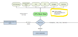
    My board can standalone boot up, and operate is normal.

    But, when the reset occur on CPU1 - WDT reset or  the reset occur on CPU2 to trig CPU1 - NMIWDT ISR timeout reset, the CPU1 cannot reset success.

    I refernced TI example code - CPU2 WDT reset & CPU1 NMIWDT ISR trig to reset CPU2 can success. So, I think CPU2 reset is OK.

    Another TI example code - CPU1 WDT ISR isn't match my application, this example code set WDT mode is ISR mode, so I didn't test.

    By the way, when I reset CPU1, and then using JTAG connect to download code & restart, I can see the WDT REG - WDRSn ( watchdog reset flag ) is ON. I think CPU1 WDT function is normal, but restart is fail.

    Hence, I want to know how to solve the question of CPU1 WDT reset or NMIWDT reset?

    Thanks.

B.R.
Bolt

  • Hi,

    When you say restart fails, what exactly happening when you restart ? Does it get stuck at some point in BOOTROM or in your application ? 

    Vivek Singh

  • Hi,

        I used JTAG to monitor the address.

        In App mode, CPU1 start address was 0x08463B and CPU2 start address was 0x0E2F44.

        When CPU1 WDT reset, CPU1 got stuck at 0x3FB181 in BOOTROM and CPU2 got stuck at 0x0E2F44 in APP.

        So, I think that the CPU1 got stuck in BOOTROM. CPU1 cannot go into the APP code.

        How do I resolve the question?

    B.R.
    Bolt

  • It could be that when WDT reset is happening, CPU2 is halted in CCS and not running ? 

  • Hi Vivek,

       I don't think so.

       When I didn't connect to CCS, the F28p65 can standalone power up success into APP, but it cannot wake up success by WDT reset too.

       So I connect to CCS, and I found the situation that just mentioned before.

       The CPU2 is ready to APP, the waiting address was in APP start address, so I think this situation wasn't CPU2 affect CPU1 to cause CPU1 halt in BOOTROM.

      Or, please tell me some detail about the situation of your describe. Why did the situation of CPU2 already wait to APP start address will let CPU1 was halted in BOOTROM?

      If you think any situation or test method, please tell me how to do, let me try it.

      If you have example code can let CPU1 success to execute WDT reset or NMIWDT reset, please let me reference, thanks.

    B.R.
    Bolt

  • Hi,

      Or, please tell me some detail about the situation of your describe. Why did the situation of CPU2 already wait to APP start address will let CPU1 was halted in BOOTROM?

    I was thinking If CCS is connected and CPU2 is halted then CPU code will not run and CPU1 may wait for handshake from CPU2 but look like that is not the case. 

      If you think any situation or test method, please tell me how to do, let me try it.

    In this case I would suggest to load the BOOTROM symbol  (<C2000Ware>\libraries\boot_rom\f28P65x\rev0\rom_sources\cpu1\ccs_files\Release) and see what exactly CPU1 is waiting for. 

    Regards,

    Vivek Singh

  • Hi Vivek,

        Thanks for your response, but I didn't clearly understand the assembly code of BOOTROM code.

        So I tried another test method, I changed my HW board from our application board to F28P65x control card.

        For the F28P65x control card, CPU2 WDT reset trig CPU1 to NMIWDT reset success.

        Hence, the layout of our application board is affect WDT reset function.

        Please give me some information of board layout to let me fix the question, thanks.

    B.R.
    Bolt

  • Bolt,

        Please give me some information of board layout to let me fix the question, thanks.

    You can find the detail in C2000Ware (<C2000Ware>\boards\controlCARDs\TMDSCNCD28P65X\RevA\documentation)

    Vivek Singh

  • Hi,

    Let me know if you have any further query on this topic,

    Vivek Singh

  • Hi Vivek,

        Sorry about to delay reply this issue.

        I readed the detail of the board layout in C2000Ware's document. 

        I cannot find the problem between the two boards. So I let HW team to check it.

        By the way, our OSC CLK is 20 MHz, do you think this difference is the problem?

        This moment, the issue is still unresolved. If I have any question, I will reply this issue again, thanks.

    B.R.
    Bolt

  • Hi,

    By the way, our OSC CLK is 20 MHz, do you think this difference is the problem?

    That should not cause any issue. 

    Vivek Singh

  • Hi Vivek,


         In TRM4.5.1 Boot Flow - Figure 4-1 Device Boot Flow, I didn't understand the description : "HW: WDG enabled Set Clock Divider to /4 Enable ECC". Is this description about Hardware layout ?

         Can you explan this description? Maybe this is the key to solve this issue.

    B.R.
    Bolt

  • That statement is about some of the action taken by BOOTCODE and nothing to do with board layout. 

    On below -

      By the way, our OSC CLK is 20 MHz, do you think this difference is the problem?

    Since you have 20MHz OSC, have you updated the PLL setting properly to make sure clock is with-in defined spec.

    Vivek Singh

  • Hi Vivek,

         Thanks your explain

         When my app initialize, the program executes InitSysPll( ) to set PLL is 20MHz.

         Have others setting need to do?

         I test HW XRST pin set low to reboot system can success. 

         Up to now, I summarize two conclusions on the reboot test.

             1. Our board can POR and XRST reboot system success, but it cannot WDT and NMIWDT reboot.
                 -> Our board's IC Version = F28P650DK9 ZEJ $7A

             2. Our code can WDT and NMIWDT reboot success on TI's control card even the app code set PLL is 20MHz.
                 -> TI's control card IC Version = XF28P650DK9 ZEJ $7

        By upon describe, do you have any suggest let me fix the bug of HW or SW?

        Does the difference of IC Revision 0 & A make the issue?

        When WDT & NMIWDT reset occurs, does the boot flow need to read some pin information? If so, please give me the pin information, thanks.

    B.R.
    Bolt

  • Hi,

    When my app initialize, the program executes InitSysPll( ) to set PLL is 20MHz.

    Do you mean 200MHz ? Can you send me the snapshot of the function call ?

        Does the difference of IC Revision 0 & A make the issue?

    No, that should not make any difference.

        When WDT & NMIWDT reset occurs, does the boot flow need to read some pin information?

    Boot flow only reads the BOOTMODE PIN value to boot the device after any reset. 

    Please note that WDT and NMIWDT reset will also toggle XRSn pin (XRST ) so behavior should be same. 

    Regards

    Vivek Singh

  • Hi Vivek,

         Thanks your reply.

      About SW code :

         My code is refernce : C2000Ware_5_01_00_00\device_support\f28p65x\common\source\f28p65x_sysctrl.c

         When initial, main()  call the function of InitSysCtrl( ) to do PLL set.

         For modify OSC 20MHz, I just modify the function of InitSysCtrl( ) as below figure.


        The callee function : InitSysPll( ) just reference f28p65x_sysctrl.c, it didn't modify.

        Is this PLL setting correct?

      About HW layout :

        Is toggle XRSn pin (XRST ) belong SW control ?

        If XRSn pin is pull high by HW configuration, does WDT and NMIWDT reset to toggle XRSn fail?

    B.R.
    Bolt

  • I'll check the SW part and get back to you.

        Is toggle XRSn pin (XRST ) belong SW control ?

    No, XRSn pin will always toggle on WD and NMIWD reset. 

        If XRSn pin is pull high by HW configuration, does WDT and NMIWDT reset to toggle XRSn fail?

    It might have impact based on the pull-up value. I would suggest to scope the XRSn pin and see if this is getting toggle when device issues WD/NMIWD reset. If possible, please share the scope capture.

    Vivek Singh

  • Hi Vivek,

        Do you check the SW part that has any problem?

        Thank you provide the HW informaiton, I will check the pin pull-up value.

    B.W.
    Bolt

  • Do you check the SW part that has any problem?

    SW looks ok to me. You can try to bring out XCLKOUT and check the clock frq.

    Vivek Singh 

  • Hi Vivek,

       Our HW team modify the XRSn pin's pull-up state, and then the WDT & NMIWDT reset are success.

       The problem is XRSn pin's GPIO reset control from another IC, when this IC doesn't output low, it always output high cause WDT & NMIWDT cannot HW toggle success. So our HW team modify this problem to let WDT & NMIWDT can toggle XRSn pin success to reset system done.

        Thanks your support.

    B.W.
    Bolt