Other Parts Discussed in Thread: C2000WARE, SYSCONFIG
Hello:
I encountered such a problem when configuring HRPWM with the TMS320F28335 series chip. The configuration code is as follows:
void
HRPWM6_Config(period)
{
//
// ePWM6 register configuration with HRPWM
// ePWM6A toggle high/low with MEP control on falling edge
//
EPwm6Regs.TBCTL.bit.PRDLD = TB_IMMEDIATE; // set Immediate load
EPwm6Regs.TBPRD = period-1;
EPwm6Regs.CMPA.half.CMPA = 0;// set duty control only by CMPAHR
EPwm6Regs.CMPA.half.CMPAHR = (255<< 8); // initialize HRPWM extension
EPwm6Regs.TBPHS.all = 0;
EPwm6Regs.TBCTR = 0;
EPwm6Regs.TBCTL.bit.CTRMODE = TB_COUNT_DOWN;//count down mode
EPwm6Regs.TBCTL.bit.PHSEN = TB_DISABLE; // ePWM6 is the Master
EPwm6Regs.TBCTL.bit.SYNCOSEL = TB_SYNC_DISABLE;
EPwm6Regs.TBCTL.bit.HSPCLKDIV = TB_DIV1;
EPwm6Regs.TBCTL.bit.CLKDIV = TB_DIV1;
EPwm6Regs.CMPCTL.bit.LOADAMODE = CC_CTR_ZERO;
EPwm6Regs.CMPCTL.bit.LOADBMODE = CC_CTR_ZERO;
EPwm6Regs.CMPCTL.bit.SHDWAMODE = CC_SHADOW;
EPwm6Regs.CMPCTL.bit.SHDWBMODE = CC_SHADOW;
EPwm6Regs.AQCTLA.bit.ZRO = AQ_CLEAR; // PWM toggle high/low
EPwm6Regs.AQCTLA.bit.CAD = AQ_SET;
//EPwm6Regs.AQCTLB.bit.PRD = AQ_CLEAR;
//EPwm6Regs.AQCTLB.bit.CBU = AQ_CLEAR;
EALLOW;
EPwm6Regs.HRCNFG.all = 0x0;
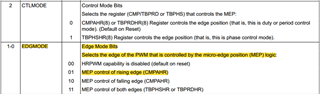
EPwm6Regs.HRCNFG.bit.EDGMODE = HR_REP; // MEP control on raising edge
EPwm6Regs.HRCNFG.bit.CTLMODE = HR_CMP;
EPwm6Regs.HRCNFG.bit.HRLOAD = HR_CTR_ZERO;
EDIS;
}
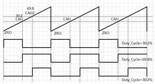
In the main function, I configure SYSCLKOUT=150MHz and TBCLK=150MHz, and pass 100 as the period parameter into the HRPWM6_Config(period) function, so the generated PWM frequency is 1.5MHz. Now the duty cycle is required to be 30.2%. When the high resolution edge is set as the falling edge, the PWM output is set up when CNT=ZRO, and the values of CMPA and CMPAHR are calculated according to the formula:
Assuming that the MEP step is 150ps, it corresponds to the SYSCLK frequency of 150MHz, and the corresponding MEPScaleFactor=44.44
![]()
The CMPA=integer(100*30.2%)=30;
The CMPAHR=(fraction(100*30.2%)*(MEPScaleFactor)+0.5(rounding))<<8=(0.2*44.44+0.5)<<8=2403;
Finally, according to the obtained CMPA and CMPAHR values, the PWM waveform with a duty cycle of about 30.2% can be obtained.
However, when configured with high resolution rising edge regulation, when CNT reaches the CMPA value calculated according to the above formula, after MEP edge control regulation, the PWM waveform is set up, and when CNT=PRD, the waveform is cleared to zero, then the obtained PWM waveform duty ratio is still 30.2% as required?
According to the above results, I think the obtained PWM waveform duty cycle should be 1-30.2=69.8%, rather than the required 30.2%, and if you want to obtain the required 30.2% duty cycle, in the rising edge control should be calculated according to 60.8% CMPA and CMPAHR values, or will the hardware help automatically switch? Or should we switch the value of duty cycle according to what I said, and then recalculate the value required by CMPA and CMPAHR according to the above formula?
Best Regards,
Runhao