This thread has been locked.

If you have a related question, please click the "Ask a related question" button in the top right corner. The newly created question will be automatically linked to this question.

TMS320F280025C: new design from Launchf280025c evm. F280025c at 2.4 v of 3.3V power supply rising causes rising excessive current after that V point

Part Number: TMS320F280025C

F280025C new design from launchpad evm previous 3 years of successful work. 5 first articles are being tested.

F280025C  80pin version,  startup with only bootloader, no code s/b in new DSP?

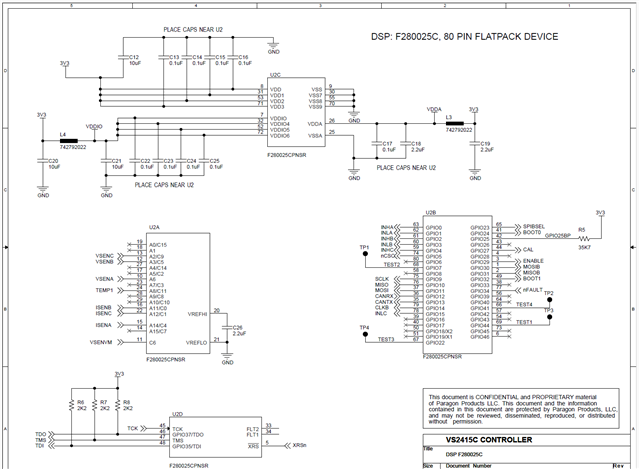
1. all 80 pins have no shorts to ground and correct 3.3 connections

2.  VDDIO and VDDA are laid out like the launch pad.  the two inductors (0.05 ohms) show now voltage drop when excessive current is at ~330ma (PS is current limited)

3.  VREFHI is directly connected to 3.3 VDD and it is assumed that this is the default acceptable reference connection since internal references not enabled.

4.  JTAG XDS110 cannot access because  DSP asserts XRSn continuously, OS slow power up -> rises to 0.8 and then down to 0.2 as expected, but never releases.  No other XRSn attached at this time

5. All traces and Gerbers look good for no shorts.

6.  F280025CPNS DSP code  $7A-34C8K5W.  a 64 is below that line

7  one possibility is that an internal starup and/or bootloader fault is a cause?

8  boot is to Flash  1,1.

a second PCB does the same thing.

This is driving a DRV8323RS 3 phase motor circuit, BUT NOT CONNECTED FOR THIS ISSUE.

I would appreciate any help.  I  have been able to finally move this company from PIC30/33 to TI and this would be a great step for all future products.   See Paragon LLC,  Folsom CA.  large locomotive fuel and other pump products.

Al Lehman,  Principal Engineer consultant to Paragon.

See "Al Lehman" in linkedin for background - 7 years Aerojet, Electrical Engineering Specialist.

  • Hi,

    4.  JTAG XDS110 cannot access because  DSP asserts XRSn continuously, OS slow power up -> rises to 0.8 and then down to 0.2 as expected, but never releases.  No other XRSn attached at this time

    Would it be possible for you to scope the VDD/VDDIO and XRSn pin and send the snapshot ?

    Vivek Singh

  • Vivek - thank you for looking at this.  Much appreciated.

    Yes I will provide that scope information.  I've done DCV measurements and the VDDIO and VDDA are identical to the PS voltages.  again I will provide the scope info.

    Just to be clear,  the problem exists with NO JTAG attached, I just tried JTAG as one of my troubleshooting process items, Nothing is attached to XRSn except 2.2K pull up resistor.

    since this starts at 2.4 volts to about 2.6V where I current limit the PS at 400 ma I'm also wondering about all of the bootstrap/diagnostics that may be involved.

    Again - thank you!!    Al

    I'll have the scope pics tues afternoon.  CA time.

  • Vivek - hear are the scope pics you asked for.  PS is about 2.6 during these.  different V for 1st two and another V for 2nd two pics.  2nd two pics have 3V3 comparison to VDDA.  first two are VDDA and VDDIO.

  • Thanks for the snapshot. Power supply looks ok. If you have not programmed anything in flash and boot mode is set to 1'1 then device may get reset because of ITRAP. Can you try changing the bootmode pin to some other value and see if that helps ?

    Vivek Singh

  • Vivek - thank you !   I will do that.  I'll set to SCI, recommended in the spec sheet somewhere, can't remember exactly.  May be Thursday at the latest before I get that done.

    Al Lehman

  • finally found how to continue.  Not resolved.  2.4V increasing voltage has increasing current from 34 ma to 500 ma at 2.6 V where my PS current limits.  set to SCI no difference.

    XRSn stays at 0.3 V+- with no other connections on the XRSn circuit (i.e. XDS110 not connected)

    Cheers

    Al Lehman

  • Will you be ok to share your board schematic ? 

  • Yes, I'll be glad to.  thank you for asking.   I'll upload tomorrow by noon. (thursday 4/11)

    please note that the same problem exists with and without the 8323RS 3v3 power supply hooked up.  right now I've removed the inductor for the 3v3.  24V applied to the 8323 side is about 2 ma,  and the 3v3 separate supply is the run away with either 8323RS 3v3 or external.

    I was sick for a few days but back now.

    thank you.

    al

  • this is the DSP page.  the design uses LaunchXL F280025c with DRV8323RS, which I've been using for a long time running several motors.

    If you need further overall information let me know.  I'll have to send privately for cover ND issues, but it is not a problem.  

    Again I've been testing with external 3v3 to isolate the issue in this area.  no excessive current in the 24V 8323RS area and I've removed the inductor for the 3v3 to isolate.  Same results with or without 8323RS 3v3 or isolated external 3v3.

    thank you.

    Al Lehman

  • Thanks. We'll have a look and get back to you. I'll also request you to re-check the signal integrity on the board for any potential issue.

  • Vivek - Yes I will re-check.   I have been going over a blank board also.

    thanx again

    al

  • Hi,

    One quick observation. In this schematic, you are connecting all VDD signals to 3V3 rail instead of 1V2. This will definitely cause issue so please fix this.

    Regards,

    Vivek Singh 

  • thank you !!  I'll change/test immediately.  Sorry about my ignorance about the internal supply.  I really appreciate your time because I was not seeing this issue.   Much appreciated.

    I'll mark resolved.