Part Number: TMS320F28379D
Hi,
I am working on a C2000 to integrate with HIL. The microcontroller is supposed to be a mc for inverter. The AC frequency of the signals that are being read by ADC's is 500 Hz. I have used this setup but it was for 60 Hz application. In this application, the AC signal is routed through DACA and DACB to the converter inside the HIL. The problem with 500 Hz signal is that when it is routed through DAC, it is no a constant signal.
To be simple, lets suppose i generated a 500 Hz sine wave signal and routed to DAC using the following code:
alpha = sin(2*3.14*500*t);
m_alpha = alpha * 2048 + 2048;
t = remainderf(t+1*qi_ctrl.Ts, 10000);
DAC_setShadowValue(DACB_BASE, m_alpha);
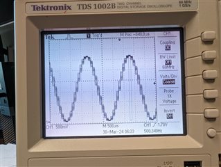
This code is being run in a timer interrupt and the period for it is 100e-6 s. Instead of getting a sine wave with 20 constant steps based on the timings, what I get is a sine signal on which the steps are riding. I am attaching a picture for your reference. I can't maintain a constant 500 Hz signal at the DAC output which is messing up my system. Is there anyway to make the timer more accurate so that the signal stays constant?
I have tried to use a much simpler example than what the application is for. But essentially, you can think like I am reading a 500 Hz signal signal from ADC and routing it to DAC and I am not getting a stable sine wave but step riding the sine wave.
Is there anyway to solve this issue?
Thanks
-
Hatif
Hatif