


Part Number: TMS320F280039C
Other Parts Discussed in Thread: ADS7038
Hi,
I am using ADS7038 and TMS39C controller for reading 7 analog signals.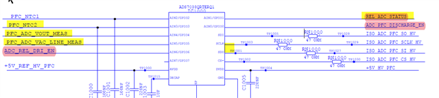
The YELLOW highlighted pins are getting high unwantedly.
ADS7038 SPI initialization function:
void SPI_init(){
	PFC_SPI_init();
}

void PFC_SPI_init(){
	SPI_disableModule(PFC_SPI_BASE);
	SPI_setConfig(PFC_SPI_BASE, DEVICE_LSPCLK_FREQ, SPI_PROT_POL0PHA1,
				  SPI_MODE_CONTROLLER, 1000000, 8);
	SPI_setPTESignalPolarity(PFC_SPI_BASE, SPI_PTE_ACTIVE_LOW);
	SPI_enableFIFO(PFC_SPI_BASE);
	SPI_disableLoopback(PFC_SPI_BASE);
	SPI_setEmulationMode(PFC_SPI_BASE, SPI_EMULATION_FREE_RUN);
	SPI_enableModule(PFC_SPI_BASE);
}

static const uint16_t ADC_Sys_Ex_StartupConfig_a16 [] = {
        ADC_EXT_WR_REG,0x10,0x00, /* Disable a current on going conversion. */
        ADC_EXT_WR_REG,0x01,0x00, /* Reset the configuration at [. */
        ADC_EXT_WR_REG,0x02,0x10, /* Append a 4-bit channel ID to the measured data. */
        ADC_EXT_WR_REG,0x03,0x00, /* Oversampling is deactivated. */
        ADC_EXT_WR_REG,0x04,0x00, /* 1 MHz sample rate + Auto sequence mode. */
        ADC_EXT_WR_REG,0x05,0xC3, /* CH0,CH1,CH6,CH7 configured as Digital and CH2,3,4,5 are configured as Analog*/
        ADC_EXT_WR_REG,0x12,0x7F, /* CH0, CH1, CH2, CH3, CH4, CH5 and CH6  are enabled for the auto sequence mode. */
        ADC_EXT_WR_REG,0x10,0x11, /* Start the auto sequence mode. */
};


static const uint16_t ADC_Sys_Ex_StartupConfigReadback_a16 [] = {
        ADC_EXT_RD_REG,0x10,0x00, /* Disable a current on going conversion. */
        ADC_EXT_RD_REG,0x01,0x00, /* Reset the configuration at startupd. */
        ADC_EXT_RD_REG,0x02,0x00, /* Append a 4-bit channel ID to the measured data. */
        ADC_EXT_RD_REG,0x03,0x00, /* Oversampling is deactivated. */
        ADC_EXT_RD_REG,0x04,0x00, /* 1 MHz sample rate + Auto sequence mode. */
        ADC_EXT_RD_REG,0x05,0x00, /* All channels are configured as analog input. */
        ADC_EXT_RD_REG,0x12,0x00, /* CH0, CH1, CH2 and CH3 are enabled for the auto sequence mode. */
        0x00,0x00,0x00            /* One additional row with dummy data to read out the last register. */
};

static uint16_t ADC_Sys_Ex_StartupConfig_Length_u16 = 8u;
static uint16_t ADC_Sys_Ex_StartupConfigReadback_Length_u16 = 8u;

void ADC_ExternalInit( void )
{
        uint16_t i = 0;
        static uint16_t tmp_Error_uint16_t = FALSE;

        /* Write the configuration of the external ADC, instead of the last entry, that is activating the auto sequence mode. */
        for ( i=0 ;i < ( ADC_Sys_Ex_StartupConfig_Length_u16 - 1u );i++ )
        {
                SPI_transmitNBytes(SPIB_BASE,(uint16_t *)&ADC_Sys_Ex_StartupConfig_a16[i*3], (uint16_t)3, (uint16_t)0);

        }

        /* Readback the registers hat has been previously written to ensure the correct operation. */
        for ( i=0;i<ADC_Sys_Ex_StartupConfigReadback_Length_u16;i++ )
        {
                /* Write three times eight bit = 24-Bits in total. */
            SPI_transmitNBytes(SPIB_BASE,(uint16_t *)&ADC_Sys_Ex_StartupConfigReadback_a16[i*3], 3, 0);

            if ( i >= 1u )
            {
                if ((SPI_M_READ_BUFFER) != ADC_Sys_Ex_StartupConfig_a16[((i-1u)*3u)+2u] << 16 )
                {
                    tmp_Error_uint16_t = TRUE;
                }
            }
        }

        /* Check if an error is present during the external ADC setup. */
        if ( tmp_Error_uint16_t == ( uint16_t ) TRUE )
        {
                ADC_Sys_Ex_ADCInit_uint16_t = FALSE;

        }
        else
        {
                ADC_Sys_Ex_ADCInit_uint16_t = TRUE;
                /* Activate the auto sequence mode at the end of the init phase. */
                SPI_transmitNBytes(SPIB_BASE,(uint16_t *)&ADC_Sys_Ex_StartupConfig_a16[(ADC_Sys_Ex_StartupConfig_Length_u16-1u)*3u], 3, 0);

        }
}
SPI re Initialized for 16 bit words and MODE 0:
void PFC_SPI_Cyclic_init(){
SPI_disableModule(PFC_SPI_BASE);
SPI_setConfig(PFC_SPI_BASE, DEVICE_LSPCLK_FREQ, SPI_PROT_POL0PHA0,
SPI_MODE_CONTROLLER, PFC_SPI_BITRATE_CYCLIC_INIT, 16);
SPI_setPTESignalPolarity(PFC_SPI_BASE, SPI_PTE_ACTIVE_LOW);
SPI_enableFIFO(PFC_SPI_BASE);
SPI_setFIFOInterruptLevel(PFC_SPI_BASE, SPI_FIFO_TXEMPTY, SPI_FIFO_RX1);
SPI_clearInterruptStatus(PFC_SPI_BASE, SPI_INT_RXFF);
SPI_enableInterrupt(PFC_SPI_BASE, SPI_INT_RXFF);
SPI_disableLoopback(PFC_SPI_BASE);
SPI_setEmulationMode(PFC_SPI_BASE, SPI_EMULATION_FREE_RUN);
SPI_enableModule(PFC_SPI_BASE);
}
DMA configured:
void PFC_SPI_RX_DMA_init(){
DMA_setEmulationMode(DMA_EMULATION_FREE_RUN);
DMA_configAddresses(PFC_SPI_RX_DMA_BASE, Rdata, PFC_SPI_RX_DMA_ADDRESS);
DMA_configBurst(PFC_SPI_RX_DMA_BASE, 1U, 0, 1);
DMA_configTransfer(PFC_SPI_RX_DMA_BASE, 1U, 0, 0);
DMA_configWrap(PFC_SPI_RX_DMA_BASE, 65535U, 0, 65535U, 0);
DMA_configMode(PFC_SPI_RX_DMA_BASE, PFC_SPI_RX_DMA_TRIGGER, DMA_CFG_ONESHOT_ENABLE | DMA_CFG_CONTINUOUS_ENABLE | DMA_CFG_SIZE_16BIT);
DMA_enableTrigger(PFC_SPI_RX_DMA_BASE);
DMA_startChannel(PFC_SPI_RX_DMA_BASE);
}
void SPIB_controller_TX_DMA_init(){
DMA_setEmulationMode(DMA_EMULATION_FREE_RUN);
DMA_configAddresses(SPIB_controller_TX_DMA_BASE, DMA_SPI_Tx_DESTADDRESS, srcAddr);
DMA_configBurst(SPIB_controller_TX_DMA_BASE, 1U, 0, 0);
DMA_configTransfer(SPIB_controller_TX_DMA_BASE, 1U, 0, 0);
DMA_configWrap(SPIB_controller_TX_DMA_BASE, 65535U, 0, 65535U, 0);
DMA_configMode(SPIB_controller_TX_DMA_BASE, DMA_TRIGGER_TINT0, DMA_CFG_ONESHOT_ENABLE | DMA_CFG_CONTINUOUS_ENABLE | DMA_CFG_SIZE_16BIT);
DMA_enableTrigger(SPIB_controller_TX_DMA_BASE);
DMA_startChannel(SPIB_controller_TX_DMA_BASE);
}
I've configured 2 DMA channels, 1 for sending data every 100us at timer interrupt to TX_BUFF and 2nd for receiving the data from RX_BUFF to an union variable. where according to the CHANNEL ID, I'm retriving the data and stroring it in its respective variable.
Code for assigning the ADC count to the resp. variable/* Defines for the channel IDs of the external ADC. */
#define ADC_PFC_DISCHARGE_EN_ID 0
#define REL_ADC_STATUS_ID 1
#define PFC_NTC1_ID 2
#define PFC_NTC2_ID 3
#define PFC_ADC_VOUT_MEAS_ID 4
#define PFC_ADC_VAC_LINE_MEAS_ID 5
#define ADC_REL_DRI_EN_ID 6
void ADC_ReadExternalResults ( void )
{
/* Read the results of the external ADC and map it to the corresponding variable. */
/* Map the results of the external ADC to the corresponding structure. */
switch ( ex_ADC_Rx_Data.EAdcResults_st.id_u16 )
{
case ADC_PFC_DISCHARGE_EN_ID:
Test_Adc_PFC_DISCHARGE_EN_count = ex_ADC_Rx_Data.EAdcResults_st.result_u16;
break;
case REL_ADC_STATUS_ID:
Test_Rel_ADC_STATUS_count = ex_ADC_Rx_Data.EAdcResults_st.result_u16;
break;
case PFC_NTC1_ID:
Test_PFC_Ntc1_count = ex_ADC_Rx_Data.EAdcResults_st.result_u16;
break;
case PFC_NTC2_ID:
Test_PFC_Ntc2_count = ex_ADC_Rx_Data.EAdcResults_st.result_u16;
break;
case PFC_ADC_VOUT_MEAS_ID:
Test_PFC_Adc_VOUT_MEAS_count = ex_ADC_Rx_Data.EAdcResults_st.result_u16;
break;
case PFC_ADC_VAC_LINE_MEAS_ID:
Test_PFC_Adc_VAC_LINE_MEAS_count = ex_ADC_Rx_Data.EAdcResults_st.result_u16;
break;
case ADC_REL_DRI_EN_ID:
Test_ADC_Rel_DRI_EN_count = ex_ADC_Rx_Data.EAdcResults_st.result_u16;
break;
default:
/* Nothing to do in this case. */
break;
}
}
while(1)
{
ADC_ReadExternalResults ();
//VOUT and VAC sent over CAN.
canDataVar1[0] = (uint8_t)((Test_PFC_Adc_VAC_LINE_MEAS_count >> 24U) & 0x000000FFU);
canDataVar1[1] = (uint8_t)((Test_PFC_Adc_VAC_LINE_MEAS_count >> 16U) & 0x000000FFU);
canDataVar1[2] = (uint8_t)((Test_PFC_Adc_VAC_LINE_MEAS_count >> 8U) & 0x000000FFU);
canDataVar1[3] = (uint8_t)((Test_PFC_Adc_VAC_LINE_MEAS_count) & 0x000000FFU);
canDataVar1[4] = (uint8_t)((PFC_ADC_VAC_LINE_MEAS_u32 >> 24U) & 0x000000FFU);
canDataVar1[5] = (uint8_t)((PFC_ADC_VAC_LINE_MEAS_u32 >> 16U) & 0x000000FFU);
canDataVar1[6] = (uint8_t)((PFC_ADC_VAC_LINE_MEAS_u32 >> 8U) & 0x000000FFU);
canDataVar1[7] = (uint8_t)((PFC_ADC_VAC_LINE_MEAS_u32) & 0x000000FFU);
CAN_sendMessage(CANA_BASE, 1U, 8U, (uint16_t *)&canDataVar1[0]);
}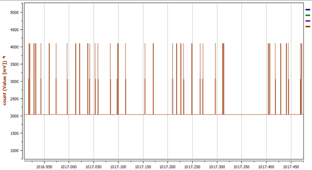
here the Input is 2048 counts which is correctly shown but randomly the pin is pulled up to 5V can you please help.
