This thread has been locked.

If you have a related question, please click the "Ask a related question" button in the top right corner. The newly created question will be automatically linked to this question.

TMS320F28P650DK: Unexpected results of force trip action

Part Number: TMS320F28P650DK


Hi TI experts,

I'm using F28P650DK9 with compiler version v22.6.1.LTS.

My goal is to software forced trip for three ePWM modules, but I couldn't trip all of them everytime I execute the code.

Here's the description of the issue:

[Case 1]

I sequentially do software forced trip to EPwm15Regs, EPwm17Regs, and EPwm18Regs, and also use EALLOW and EDIS to ensure that the registers are set correctly.

EALLOW;
EPwm15Regs.TZFRC.bit.OST = 1;
EPwm17Regs.TZFRC.bit.OST = 1;
EPwm18Regs.TZFRC.bit.OST = 1;
EDIS;

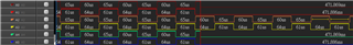
The waveforms below represents EPWM15A, EPWM15B, EPWM17A, EPWM17B, EPWM18A, EPWM18B signals. The left side of the red line indicates the normal waveform (All PWM module activate), and the right side of the red line indicates results of forced-trip action. However, only EPWM15 was not successfully tripped.

[Case 2]

I've tried to add a line of code behind for debugging. I found that the result changes, it turns out to be that EPWM17 is not tripped succesfully.

EALLOW;
EPwm15Regs.TZFRC.bit.OST = 1;
EPwm17Regs.TZFRC.bit.OST = 1;
EPwm18Regs.TZFRC.bit.OST = 1;
GpioDataRegs.GPCTOGGLE.bit.GPIO68 = 1;
EDIS;

I would like to ask how to explain two cases above, or is there a problem with my register settings?

  • Sorry, please notice that It's a new question, not a related question from "TMS320F28P650DK: VerifyXTAL() Fail reason". 

  • Hi Andy,

    I will discuss this question with other PWM experts, this case may have been encountered before on F28P65x.

    Thank you,

    Luke

  • Hi Andy,

    Apologies for the delayed response. Are you still seeing this issue?

    Thank you,

    Luke

  • Yes, I still want to know the reasons of this problem.

  • Okay, would you be able to send your code or any code that can reproduce this issue on a F28P65x launchpad or control card? I will test on my side to determine the root cause.

  • Hello, I also have the same issue. Can replicate the same way mentioned in the original post - configure several EPWMs (in my case with TZA and TZB for all set to force output low), attempted to force a software trip on all of them by setting OST, notice that some EPWMs are still enabled. Using the same code on an older target (such as the 28379d) works fine. Testing using a LaunchPad.

  • Hi Sean,

    I am working on recreating this issue on my side, will respond back with my results sometime this week.

    Thank you,

    Luke

  • Much appreciated! I have attached an example that readily replicates the issue as well. It is a modification of the "epwm_ex1_trip_zone" example, using the changed .c and syscfg file I attached. The program sets up EPWMs 1 and 2, then calls a software forced trip on both of them. Running the code however reveals that only EPWM 2 is properly disabled, EPWM1 is still running fine. Let me know if your findings are consistent with my experience. I tried MANY different variations to try to find a workaround but was unable to do so - for some reason occasionally calls to this software force seemingly do nothing (TZFLG.OST is not set despite writing 1 to the TZFRC.OST bit).

    //#############################################################################
    //
    // FILE:   epwm_ex1_trip_zone.c
    //
    // TITLE:  ePWM Using Trip-Zone Submodule.
    //
    //! \addtogroup driver_example_list
    //! <h1>ePWM Trip Zone</h1>
    //!
    //! This example configures ePWM1 and ePWM2 as follows
    //!  - ePWM1 has TZ1 as one shot trip source
    //!  - ePWM2 has TZ1 as cycle by cycle trip source
    //!
    //! Initially tie TZ1 high. During the test, monitor ePWM1 or ePWM2
    //! outputs on a scope. Pull TZ1 low to see the effect.
    //!
    //!  \b External \b Connections \n
    //!  - ePWM1A is on GPIO0
    //!  - ePWM2A is on GPIO2
    //!  - TZ1 is on GPIO12
    //!
    //! This example also makes use of the Input X-BAR. GPIO12 (the external
    //! trigger) is routed to the input X-BAR, from which it is routed to TZ1.
    //!
    //! The TZ-Event is defined such that ePWM1A will undergo a One-Shot Trip
    //! and ePWM2A will undergo a Cycle-By-Cycle Trip.
    //!
    //              _____________             __________________
    //              |           |             |                |
    //  GPIO12 -----| I/P X-BAR |-----TZ1-----| ePWM TZ Module |-----TZ-Event
    //              |___________|             |________________|
    //
    //
    //
    //#############################################################################
    //
    //
    // $Copyright:
    // Copyright (C) 2022 Texas Instruments Incorporated - http://www.ti.com
    //
    // Redistribution and use in source and binary forms, with or without 
    // modification, are permitted provided that the following conditions 
    // are met:
    // 
    //   Redistributions of source code must retain the above copyright 
    //   notice, this list of conditions and the following disclaimer.
    // 
    //   Redistributions in binary form must reproduce the above copyright
    //   notice, this list of conditions and the following disclaimer in the 
    //   documentation and/or other materials provided with the   
    //   distribution.
    // 
    //   Neither the name of Texas Instruments Incorporated nor the names of
    //   its contributors may be used to endorse or promote products derived
    //   from this software without specific prior written permission.
    // 
    // THIS SOFTWARE IS PROVIDED BY THE COPYRIGHT HOLDERS AND CONTRIBUTORS 
    // "AS IS" AND ANY EXPRESS OR IMPLIED WARRANTIES, INCLUDING, BUT NOT 
    // LIMITED TO, THE IMPLIED WARRANTIES OF MERCHANTABILITY AND FITNESS FOR
    // A PARTICULAR PURPOSE ARE DISCLAIMED. IN NO EVENT SHALL THE COPYRIGHT 
    // OWNER OR CONTRIBUTORS BE LIABLE FOR ANY DIRECT, INDIRECT, INCIDENTAL, 
    // SPECIAL, EXEMPLARY, OR CONSEQUENTIAL DAMAGES (INCLUDING, BUT NOT 
    // LIMITED TO, PROCUREMENT OF SUBSTITUTE GOODS OR SERVICES; LOSS OF USE,
    // DATA, OR PROFITS; OR BUSINESS INTERRUPTION) HOWEVER CAUSED AND ON ANY
    // THEORY OF LIABILITY, WHETHER IN CONTRACT, STRICT LIABILITY, OR TORT 
    // (INCLUDING NEGLIGENCE OR OTHERWISE) ARISING IN ANY WAY OUT OF THE USE 
    // OF THIS SOFTWARE, EVEN IF ADVISED OF THE POSSIBILITY OF SUCH DAMAGE.
    // $
    //#############################################################################
    
    //
    // Included Files
    //
    #include "driverlib.h"
    #include "device.h"
    #include "board.h"
    
    //
    // Globals
    //
    uint32_t  epwm1TZIntCount;
    uint32_t  epwm2TZIntCount;
    
    //
    // Function Prototypes
    //
    __interrupt void epwm1TZISR(void);
    __interrupt void epwm2TZISR(void);
    
    void main(void)
    {
        //
        // Initialize global variables
        //
        epwm1TZIntCount = 0U;
        epwm2TZIntCount = 0U;
    
        //
        // Initialize device clock and peripherals
        //
        Device_init();
    
        //
        // Disable pin locks and enable internal pull-ups.
        //
        Device_initGPIO();
    
        //
        // Initialize PIE and clear PIE registers. Disables CPU interrupts.
        //
        Interrupt_initModule();
    
        //
        // Initialize the PIE vector table with pointers to the shell Interrupt
        // Service Routines (ISR).
        //
        Interrupt_initVectorTable();
    
        //
        // Disable sync(Freeze clock to PWM as well)
        //
        SysCtl_disablePeripheral(SYSCTL_PERIPH_CLK_TBCLKSYNC);
    
        //
        // Configure ePWM1, ePWM2, and TZ GPIOs/Modules
        //
        Board_init();
    
        EPWM_forceTripZoneEvent(myEPWM1_BASE, EPWM_TZ_FORCE_EVENT_OST);
        EPWM_forceTripZoneEvent(myEPWM2_BASE, EPWM_TZ_FORCE_EVENT_OST);
        //
        // Enable sync and clock to PWM
        //
        SysCtl_enablePeripheral(SYSCTL_PERIPH_CLK_TBCLKSYNC);
    
        //
        // Enable Global Interrupt (INTM) and real time interrupt (DBGM)
        //
        EINT;
        ERTM;
    
        //
        // IDLE loop. Just sit and loop forever (optional):
        //
        for(;;)
        {
            NOP;
        }
    }
    
    //
    // epwm1TZISR - ePWM1 TZ ISR
    //
    __interrupt void epwm1TZISR(void)
    {
        epwm1TZIntCount++;
    
        //
        // To re-enable the OST Interrupt, uncomment the below code:
        //
        // EPWM_clearTripZoneFlag(EPWM1_BASE,
        //                        (EPWM_TZ_INTERRUPT | EPWM_TZ_FLAG_OST));
    
        //
        // Acknowledge this interrupt to receive more interrupts from group 2
        //
        Interrupt_clearACKGroup(INT_myEPWM1_TZ_INTERRUPT_ACK_GROUP);
    }
    
    //
    // epwm2TZISR - ePWM2 TZ ISR
    //
    __interrupt void epwm2TZISR(void)
    {
        epwm2TZIntCount++;
    
        //
        // Toggle GPIO to notify when TZ is entered
        //
        GPIO_togglePin(myGPIO11);
    
        //
        // Clear the flags - we will continue to take this interrupt until the TZ
        // pin goes high.
        //
        //EPWM_clearTripZoneFlag(myEPWM2_BASE, (EPWM_TZ_INTERRUPT | EPWM_TZ_FLAG_CBC));
    
        //
        // Acknowledge this interrupt to receive more interrupts from group 2
        //
        Interrupt_clearACKGroup(INT_myEPWM2_TZ_INTERRUPT_ACK_GROUP);
    }
    
    
    /**
     * These arguments were used when this file was generated. They will be automatically applied on subsequent loads
     * via the GUI or CLI. Run CLI with '--help' for additional information on how to override these arguments.
     * @cliArgs --device "F28P65x" --package "256ZEJ" --part "F28P65x_256ZEJ" --context "CPU1" --product "C2000WARE@5.02.00.00"
     * @versions {"tool":"1.19.0+3426"}
     */
    
    /**
     * Import the modules used in this configuration.
     */
    const epwm       = scripting.addModule("/driverlib/epwm.js", {}, false);
    const epwm1      = epwm.addInstance();
    const epwm2      = epwm.addInstance();
    const gpio       = scripting.addModule("/driverlib/gpio.js", {}, false);
    const gpio1      = gpio.addInstance();
    const inputxbar  = scripting.addModule("/driverlib/inputxbar.js", {}, false);
    const inputxbar1 = inputxbar.addInstance();
    
    /**
     * Write custom configuration values to the imported modules.
     */
    epwm1.useCase                                                    = "CUSTOM";
    epwm1.useInterfacePins                                           = ["EPWM#_A"];
    epwm1.$name                                                      = "myEPWM1";
    epwm1.epwmTimebase_period                                        = 12000;
    epwm1.epwmTimebase_counterMode                                   = "EPWM_COUNTER_MODE_UP_DOWN";
    epwm1.epwmTimebase_clockDiv                                      = "EPWM_CLOCK_DIVIDER_4";
    epwm1.epwmTimebase_hsClockDiv                                    = "EPWM_HSCLOCK_DIVIDER_4";
    epwm1.epwmCounterCompare_cmpA                                    = 6000;
    epwm1.epwmActionQualifier_EPWM_AQ_OUTPUT_A_ON_TIMEBASE_UP_CMPA   = "EPWM_AQ_OUTPUT_HIGH";
    epwm1.epwmActionQualifier_EPWM_AQ_OUTPUT_A_ON_TIMEBASE_DOWN_CMPA = "EPWM_AQ_OUTPUT_LOW";
    epwm1.epwmTripZone_registerInterrupts                            = true;
    epwm1.epwmTripZone_oneShotSource                                 = ["EPWM_TZ_SIGNAL_OSHT1"];
    epwm1.epwmTripZone_tzInterruptSource                             = ["EPWM_TZ_INTERRUPT_OST"];
    epwm1.epwmTripZone_EPWM_TZ_ACTION_EVENT_TZB                      = "EPWM_TZ_ACTION_LOW";
    epwm1.epwmTripZone_EPWM_TZ_ACTION_EVENT_DCAEVT1                  = "EPWM_TZ_ACTION_LOW";
    epwm1.epwmTripZone_EPWM_TZ_ACTION_EVENT_DCAEVT2                  = "EPWM_TZ_ACTION_LOW";
    epwm1.epwmTripZone_EPWM_TZ_ACTION_EVENT_DCBEVT1                  = "EPWM_TZ_ACTION_LOW";
    epwm1.epwmTripZone_EPWM_TZ_ACTION_EVENT_DCBEVT2                  = "EPWM_TZ_ACTION_LOW";
    epwm1.epwmTripZone_EPWM_TZ_ACTION_EVENT_TZA                      = "EPWM_TZ_ACTION_LOW";
    epwm1.epwm.$assign                                               = "EPWM1";
    epwm1.epwm.epwm_aPin.$assign                                     = "GPIO0";
    epwm1.epwmTZInt.interruptHandler                                 = "epwm1TZISR";
    epwm1.epwmTZInt.enableInterrupt                                  = true;
    
    epwm2.useCase                                                    = "CUSTOM";
    epwm2.useInterfacePins                                           = ["EPWM#_A"];
    epwm2.$name                                                      = "myEPWM2";
    epwm2.epwmTimebase_period                                        = 6000;
    epwm2.epwmTimebase_counterMode                                   = "EPWM_COUNTER_MODE_UP_DOWN";
    epwm2.epwmTimebase_clockDiv                                      = "EPWM_CLOCK_DIVIDER_4";
    epwm2.epwmTimebase_hsClockDiv                                    = "EPWM_HSCLOCK_DIVIDER_4";
    epwm2.epwmCounterCompare_cmpA                                    = 3000;
    epwm2.epwmActionQualifier_EPWM_AQ_OUTPUT_A_ON_TIMEBASE_UP_CMPA   = "EPWM_AQ_OUTPUT_HIGH";
    epwm2.epwmActionQualifier_EPWM_AQ_OUTPUT_A_ON_TIMEBASE_DOWN_CMPA = "EPWM_AQ_OUTPUT_LOW";
    epwm2.epwmTripZone_registerInterrupts                            = true;
    epwm2.epwmTripZone_EPWM_TZ_ACTION_EVENT_TZB                      = "EPWM_TZ_ACTION_LOW";
    epwm2.epwmTripZone_EPWM_TZ_ACTION_EVENT_DCAEVT1                  = "EPWM_TZ_ACTION_LOW";
    epwm2.epwmTripZone_EPWM_TZ_ACTION_EVENT_DCBEVT1                  = "EPWM_TZ_ACTION_LOW";
    epwm2.epwmTripZone_EPWM_TZ_ACTION_EVENT_TZA                      = "EPWM_TZ_ACTION_LOW";
    epwm2.epwmTripZone_EPWM_TZ_ACTION_EVENT_DCAEVT2                  = "EPWM_TZ_ACTION_LOW";
    epwm2.epwmTripZone_EPWM_TZ_ACTION_EVENT_DCBEVT2                  = "EPWM_TZ_ACTION_LOW";
    epwm2.epwmTripZone_oneShotSource                                 = ["EPWM_TZ_SIGNAL_OSHT1"];
    epwm2.epwmTripZone_tzInterruptSource                             = ["EPWM_TZ_INTERRUPT_OST"];
    epwm2.epwm.$assign                                               = "EPWM2";
    epwm2.epwm.epwm_aPin.$assign                                     = "GPIO2";
    epwm2.epwmTZInt.interruptHandler                                 = "epwm2TZISR";
    epwm2.epwmTZInt.enableInterrupt                                  = true;
    
    gpio1.$name           = "myGPIO11";
    gpio1.direction       = "GPIO_DIR_MODE_OUT";
    gpio1.qualMode        = "GPIO_QUAL_ASYNC";
    gpio1.gpioPin.$assign = "GPIO11";
    
    inputxbar1.$name = "myINPUTXBAR1";
    

  • Hi Sean,

    I am able to reproduce this issue on my side. I will reach out to the design team to confirm the root cause of this issue.

    Thank you,

    Luke

  • Hi Sean,

    I found a workaround for now that seems to resolve this issue, although I cannot explain why it works as of now.

    Simply write to TZFRC twice in a row instead of once. When I do this on my side, I always see both EPWMs get tripped. When I only write once, sometimes I see PWM1 tripped but not PWM2 or vice versa.

    I will let you know what feedback I receive from the design team.

    Thank you,

    Luke

  • This seems to work! Will definitely be curious to hear the reasoning, but happy to have a workaround in the interim. Thank you!

  • No problem, I will let you know what information I receive from the design team.

  • Hi Sean,

    The design team is currently simulating this issue, I will keep you updated.

    --Luke

  • Hi Sean,

    I will be on vacation til end of June, the design team is still working on this. I'll let you know their results once I return.

    Thank you,

    Luke

  • Hi Sean,

    If you change your EPWM clock divider (PERCLKDIVSEL.PWMDIVSEL) to 0, do you see this issue when writing to TZFRC just once?

    Thank you,

    Luke

  • It appears the issue remains yes

  • Okay, the design team responded back saying that the issue exists when PERCLKDIVSEL.PWMDIVSEL is not 0, but there is no issue when it is 0. I will share your results with them so they can clarify.

    --Luke

  • Sure thing! I'm not 100% confident I setup the test perfectly so I could be wrong. Either way definitely curious the nature of this thing!

  • Understood, let me know if you encounter any issues with your setup that might otherwise explain the issue.

    --Luke

  • The workaround seems not working in all the cases.
    In outìr application the force is done on many PWM after the same triggering event, and doubling the force is not working. Maybe we are missing something?

  • Hi Silvio,

    The design team has still not responded but I will let them know this issue is urgent. I am working on recreating the issue on my side with PERCLKDIVSEL.PWMDIVSEL = 0x0. Once I'm able to do this I will share my results with the design team so they can clarify the root cause of this issue.

    Thank you,

    Luke

  • Hi Silvio,

    I added the following line of code before Board_init(); in the code snippet shared earlier in this thread:

    SysCtl_setEPWMClockDivider(SYSCTL_EPWMCLK_DIV_1);

    After adding this, I was unable to reproduce the issue. Without this line of code, I consistently see the issue on one of the two EPWMs.

    Here is my updated main file, could you try testing on your side:

    //#############################################################################
    //
    // FILE:   epwm_ex1_trip_zone.c
    //
    // TITLE:  ePWM Using Trip-Zone Submodule.
    //
    //! \addtogroup driver_example_list
    //! <h1>ePWM Trip Zone</h1>
    //!
    //! This example configures ePWM1 and ePWM2 as follows
    //!  - ePWM1 has TZ1 as one shot trip source
    //!  - ePWM2 has TZ1 as cycle by cycle trip source
    //!
    //! Initially tie TZ1 high. During the test, monitor ePWM1 or ePWM2
    //! outputs on a scope. Pull TZ1 low to see the effect.
    //!
    //!  \b External \b Connections \n
    //!  - ePWM1A is on GPIO0
    //!  - ePWM2A is on GPIO2
    //!  - TZ1 is on GPIO12
    //!
    //! This example also makes use of the Input X-BAR. GPIO12 (the external
    //! trigger) is routed to the input X-BAR, from which it is routed to TZ1.
    //!
    //! The TZ-Event is defined such that ePWM1A will undergo a One-Shot Trip
    //! and ePWM2A will undergo a Cycle-By-Cycle Trip.
    //!
    //              _____________             __________________
    //              |           |             |                |
    //  GPIO12 -----| I/P X-BAR |-----TZ1-----| ePWM TZ Module |-----TZ-Event
    //              |___________|             |________________|
    //
    //
    //
    //#############################################################################
    //
    //
    // $Copyright:
    // Copyright (C) 2022 Texas Instruments Incorporated - http://www.ti.com
    //
    // Redistribution and use in source and binary forms, with or without 
    // modification, are permitted provided that the following conditions 
    // are met:
    // 
    //   Redistributions of source code must retain the above copyright 
    //   notice, this list of conditions and the following disclaimer.
    // 
    //   Redistributions in binary form must reproduce the above copyright
    //   notice, this list of conditions and the following disclaimer in the 
    //   documentation and/or other materials provided with the   
    //   distribution.
    // 
    //   Neither the name of Texas Instruments Incorporated nor the names of
    //   its contributors may be used to endorse or promote products derived
    //   from this software without specific prior written permission.
    // 
    // THIS SOFTWARE IS PROVIDED BY THE COPYRIGHT HOLDERS AND CONTRIBUTORS 
    // "AS IS" AND ANY EXPRESS OR IMPLIED WARRANTIES, INCLUDING, BUT NOT 
    // LIMITED TO, THE IMPLIED WARRANTIES OF MERCHANTABILITY AND FITNESS FOR
    // A PARTICULAR PURPOSE ARE DISCLAIMED. IN NO EVENT SHALL THE COPYRIGHT 
    // OWNER OR CONTRIBUTORS BE LIABLE FOR ANY DIRECT, INDIRECT, INCIDENTAL, 
    // SPECIAL, EXEMPLARY, OR CONSEQUENTIAL DAMAGES (INCLUDING, BUT NOT 
    // LIMITED TO, PROCUREMENT OF SUBSTITUTE GOODS OR SERVICES; LOSS OF USE,
    // DATA, OR PROFITS; OR BUSINESS INTERRUPTION) HOWEVER CAUSED AND ON ANY
    // THEORY OF LIABILITY, WHETHER IN CONTRACT, STRICT LIABILITY, OR TORT 
    // (INCLUDING NEGLIGENCE OR OTHERWISE) ARISING IN ANY WAY OUT OF THE USE 
    // OF THIS SOFTWARE, EVEN IF ADVISED OF THE POSSIBILITY OF SUCH DAMAGE.
    // $
    //#############################################################################
    
    //
    // Included Files
    //
    #include "driverlib.h"
    #include "device.h"
    #include "board.h"
    
    //
    // Globals
    //
    uint32_t  epwm1TZIntCount;
    uint32_t  epwm2TZIntCount;
    
    //
    // Function Prototypes
    //
    __interrupt void epwm1TZISR(void);
    __interrupt void epwm2TZISR(void);
    
    void main(void)
    {
    
        //
        // Initialize global variables
        //
        epwm1TZIntCount = 0U;
        epwm2TZIntCount = 0U;
    
        //
        // Initialize device clock and peripherals
        //
        Device_init();
    
        //
        // Disable pin locks and enable internal pull-ups.
        //
        Device_initGPIO();
    
        //
        // Initialize PIE and clear PIE registers. Disables CPU interrupts.
        //
        Interrupt_initModule();
    
        //
        // Initialize the PIE vector table with pointers to the shell Interrupt
        // Service Routines (ISR).
        //
        Interrupt_initVectorTable();
    
        //
        // Disable sync(Freeze clock to PWM as well)
        //
        SysCtl_disablePeripheral(SYSCTL_PERIPH_CLK_TBCLKSYNC);
    
        //
        // Configure ePWM1, ePWM2, and TZ GPIOs/Modules
        //
    
        SysCtl_setEPWMClockDivider(SYSCTL_EPWMCLK_DIV_1);
    
        Board_init();
    
        EPWM_forceTripZoneEvent(myEPWM1_BASE, EPWM_TZ_FORCE_EVENT_OST);
        EPWM_forceTripZoneEvent(myEPWM2_BASE, EPWM_TZ_FORCE_EVENT_OST);
        //
        // Enable sync and clock to PWM
        //
        SysCtl_enablePeripheral(SYSCTL_PERIPH_CLK_TBCLKSYNC);
    
        //
        // Enable Global Interrupt (INTM) and real time interrupt (DBGM)
        //
        EINT;
        ERTM;
    
        //
        // IDLE loop. Just sit and loop forever (optional):
        //
        for(;;)
        {
            NOP;
        }
    }
    
    //
    // epwm1TZISR - ePWM1 TZ ISR
    //
    __interrupt void epwm1TZISR(void)
    {
        epwm1TZIntCount++;
    
        //
        // To re-enable the OST Interrupt, uncomment the below code:
        //
        // EPWM_clearTripZoneFlag(EPWM1_BASE,
        //                        (EPWM_TZ_INTERRUPT | EPWM_TZ_FLAG_OST));
    
        //
        // Acknowledge this interrupt to receive more interrupts from group 2
        //
        Interrupt_clearACKGroup(INT_myEPWM1_TZ_INTERRUPT_ACK_GROUP);
    }
    
    //
    // epwm2TZISR - ePWM2 TZ ISR
    //
    __interrupt void epwm2TZISR(void)
    {
        epwm2TZIntCount++;
    
        //
        // Toggle GPIO to notify when TZ is entered
        //
        GPIO_togglePin(myGPIO11);
    
        //
        // Clear the flags - we will continue to take this interrupt until the TZ
        // pin goes high.
        //
        //EPWM_clearTripZoneFlag(myEPWM2_BASE, (EPWM_TZ_INTERRUPT | EPWM_TZ_FLAG_CBC));
    
        //
        // Acknowledge this interrupt to receive more interrupts from group 2
        //
        Interrupt_clearACKGroup(INT_myEPWM2_TZ_INTERRUPT_ACK_GROUP);
    }
    

    Thank you,

    Luke

  • Hi Luke,

    it seems like that setting SYSCTL_EPWMCLK_DIV to 1(so 200MHz ePWM) resolve the issue for us, of course we cannot be sure 100% that this issue will not happen again. Do you plan to release an errata about this? The problem appears to be HW or FW?

  • Hi Mattia,

    This appears to be an unintended in the HW that requires the FW workaround I shared with you. The design team has confirmed that this can only happen when the /2 divider is used.

    We will document this issue in the next revision of the errata.

    Thank you,

    Luke