This thread has been locked.

If you have a related question, please click the "Ask a related question" button in the top right corner. The newly created question will be automatically linked to this question.

TMS320F280039C: TMS320F280039CSPM

Part Number: TMS320F280039C
Other Parts Discussed in Thread: C2000WARE, UNIFLASH

Hello,

 We are not able to program the F280039CSPM via SCI boot mode and are trying to troubleshoot the issue.

Here is what we did so far
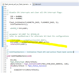
We used the flash_kernel_ex3_sci_flash_kernel.txt  from C2000Ware_x_xx_xx_xx > driverlib > f28003x > examples > flash .
No changes were made  to the source code and the build configuration used was CPU1_RAM
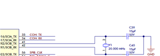
The GPIO24 was low and GPIO32 was  high and we reset the device.
Run the serial_flash_programmer using the following command

serial_flash_programmer.exe -d f28003x -k flash_kernel_ex3_sci_flash_kernel.txt -a gpio_ex2_toggle.txt -p COM7 -b 9600 -v

received the following response
C2000 Serial Firmware Upgrader
Copyright (c) 2013 Texas Instruments Incorporated.  All rights reserved.

getting comm state
building comm DCB
adjusting port settings

calling f021_DownloadKernel CPU1 Kernel
Downloading flash_kernel_ex3_sci_flash_kernel.txt to device...

Attempting autobaud to load the kernel...
It doesn't progress beyond this. 
thanks
Najma
  • Some additional information from the customer based on some of my own queries:

    1. What is the origin of flash_kernel_ex3_sci_flash_kernel.txt?
      1. Does it come from C2000Ware_x_xx_xx_xx > driverlib > f28003x > examples > flash? - Yes
      2. Did you build it from source? - Yes
      3. Did you make any source code changes? - No
      4. Which build configuration did you use? CPU1_RAM? - CPU1_RAM
    2. Are you following the correct reset procedure? I think the answer is yes. - Yes we are
      1. Hold GPIO24 low and GPIO32 high.
      2. Reset the device (Press S1 while S2 is also being held in the pressed position).
      3. Run the serial_flash_programmer.exe command.
    3. Have you modified any of the Boot Mode configuration registers of the device? - No
      1. From a debugger, you can read out BOOTPIN-CONFIG and BOOTDEF registers to validate their correct values.

    Thanks,

    Stuart

  • Hi Stuart,

    Are you sure this is using the correct COM port?

    Thanks and regards,

    Charles

  • Hi Charles ,

    We are using the correct COM port.

    thanks

    Najma

  • Hi Najma,

    Ok, in what version of C2000Ware did the SCI Flash Kernel/SCI Host programmer project come from?

    What is the device frequency being set in the device.h file for the kernel project?

    Is there a data cable for the SCI connection? That will be required.

    Thanks and regards,

    Charles

  • Najma,

    Just to clarify on what Charles mentioned above, we would want to make sure that we are using the correct pins for the SCI boot(see below)

    If you are using the controlCARD, the UART channel to the PC(through the USB C cable) is connected to GPIO28/29, but I wasn't certain if you are using controlCARD or not.  There is also another switch on the controlCARD S1:A that both need to be "on" to support both JTAG and SCI connection through the USB connection.

    If you are not using the controlCARD, then we just need to verify the connections depending on the option you have picked(if OTP has not been touched it will be same GPIO28/29).

    Best,
    Matthew

  • Hello Mathew,

    We are not using the controlCARD. 

    We are using GPIO 24 and GPIO 32 as mentioned in this table (TMS320F28003x Real-Time Microcontrollers datasheet).Our schematic was reviewed  by TI and had confirmed that we are using the correct GPIOs 

  • Najma,

    Matt is referring to the pins that the SCI UART are on. If I look at your schematic, it looks to me like you are using GPIO16 and GPIO17, but the default boot UART pins are GPIO29 and GPIO28.

    Have I interpreted your schematic correctly? I was not involved in the review of this design, so I do not have the details of that review, and if you conveyed specifics about the use case that would have cause TI to validate the [UART] boot pins.

    Thanks,

    Stuart

  • Hello Stuart,

    Sorry I was referring to boot mode pins.

    You are right. We are using GPIO16 & 17 for TX & RX. 

  • Hi Najma,

    Which C2000ware version you are using?

    What is the device frequency being set in the device.h file for the kernel project? Is it same as per your board?

    Regards,

    Rajeshwary

  • We are using C2000Ware_5_01_00_00. The clock frequency is 20MHz for our board. We haven't made any changes to the device.h file


  • Hi Najma,

    Thanks for confirmation.

    By default SCI Flash Kernel code uses SCI_BOOT i.e GPIO28,29.

    In order to change to alternate TX/Rx pins for SCI boot, you need to pass parameter as SCI_BOOT_ALT1 (GPIO16; GPIO17)  for SCI to sciGetFunction() in flash_kernel_ex3_sci_flash_kernel.c.

    #define SCI_BOOT 0x01U //GPIO29; GPIO28 (CCARD)
    #define SCI_BOOT_ALT1 0x21U //GPIO16; GPIO17
    #define SCI_BOOT_ALT2 0x41U //GPIO8; GPIO9
    #define SCI_BOOT_ALT3 0x61U //GPIO2; GPIO3
    #define SCI_BOOT_ALT4 0x81U //GPIO16; GPIO3

    These options can be found in the cpu1bootm.h file in the libraries/boot_rom_f28003 within C2000ware.

    Regards,

    Rajeshwary

  • Hi Rajeshwary,

    Code Composer Studio Version: 12.7.0.00007

    C2000Ware_5_02_00_00

    Here is what I did

    Open CCS            Project/Import CCS Projects
    Select search- directory C2000Ware_5_02_00_00\driverlib\f28003x\examples - browse
    from the list of discovered projects , selected flash_kernel_ex3_sci_flash_kernel

    opened flash_kernel_ex3_sci_flash_kernel.c and added the right parameters to sciGetFunction to add alternate TX/Rx pins for SCI boot

    //EntryAddr = sciGetFunction(SCI_BOOT);
    EntryAddr = sciGetFunction(SCI_BOOT_ALT1);
    return(EntryAddr);

    Save file
    build project and verified it generated the latest flash_kernel_ex3_sci_flash_kernel.txt

    Press the BOOT switch so that GPIO24 is low and reset the device 

    Release the switch 

    run the following command
    >serial_flash_programmer.exe -d f28003x -k flash_kernel_ex3_sci_flash_kernel.txt -a gpio_ex2_toggle.txt -p COM7 -b 9600 -v

    please see the log below

    C2000 Serial Firmware Upgrader
    Copyright (c) 2013 Texas Instruments Incorporated. All rights reserved.

    getting comm state
    building comm DCB
    adjusting port settings

    calling f021_DownloadKernel CPU1 Kernel
    Downloading flash_kernel_ex3_sci_flash_kernel.txt to device...

    Attempting autobaud to load kernel...

    It is not progressing beyond this 

    thanks

    Najma 

  • Hello,

    Is there anything that we need to change on the device.h file ? Since you confirmed that by default SCI Flash Kernel code uses SCI_BOOT i.e GPIO28,29, what are the changes required to use alternate TX/Rx pins for SCI boot. Please confirm asap.

    thanks

    Najma 

  • Najma,

    Since you are not using the default SCI UART boot pins, I believe you will also need to update the bootdef values to point to the correct pins. Otherwise, I don't think the bootrom will even look at the SCI UART pins you have chosen.

    , do I have that correct?

    Thanks,

    Stuart

  • Thanks. It would be helpful if you can tell us all the changes that's required. 

  • Have a look at this section from the TRM:

    You want to use the appropriate value from this table in the datasheet:

    Thanks,

    Stuart

  • I modified both the flash_kernel_ex3_sci_flash_kernel.c and device to h to  add alternate TX/Rx pins for SCI boot.

    But it didn't solve the problem.

    thanks

    Najma 

  • Hi Najma,

    Can you please share the code changes done?

    Regards,

    Rajeshwary

  • Hello Rajeshwary,

    - changed the parameter for SCI_BOOT

    - changed the GPIO number for SCI RX / TX

    thanks

    Najma 

  • Hi Najma,

    Thanks for the sharing code will review and get back. Also as stated by Stuart you also need to update the bootdef values to point to the correct pins.

    Regards,

    Rajeshwary

  • Hello Rajeshwary , I had updated the bootdef values via UniFlash and tried testing it again. But it didn't resolve the issue. Please let me know if you had a chance to review the code.

    thanks

    Najma 

  • Hi Najma,

    Code changes seems correct, for further opinion on SCI_BOOT from non default pin option I will ask this thread to be assign to Boot-ROM expert.

    Regards,

    Rajeshwary

  • Hello Rajeshwary,

    Please let me know if you have any updates.

    thanks

    Najma 

  • Hello Najma,

    Can you let me know if you have tried the options for custom boot modes in the TRM's section "4.4.2 Custom Boot Modes" already?

    Regards,
    Kedar

  • Hello Kedar,

    I had updated the bootdef values via UniFlash  to point to the correct SCI TX/RX pins that we are using (GPIO16, 17).

    I also modified both the flash_kernel_ex3_sci_flash_kernel.c and device.h to  add alternate TX/Rx pins for SCI boot.

    thanks

    Najma 

  • Hi Najma,

    Can you please share a dump of your DCSM registers once booted?

    Regards,
    Kedar

  • Hi Najma,
    Emulation Boot Instructions:
    1.  In CCS, import and build the CPU1 kernel project.
    2.  Launch the target configuration file.
    3.  Connect to CPU1.
    4.  Load the gel file provided in the project folder to the project. Right click on CPU1 in the target configuration and select "Open GEL Files View".
    5.  In the "GEL Files" tab, click on GEL Files. Right click in the "Script" window and select "Load GEL...". Navigate to the project folder and load the gel file.
    6.  Option 1 - In emulation mode, the following memory locations need to be set to enable SCI boot mode:
        - Location 0xD00 with 0xFFFF
        - Location 0xD01 with 0x5AFF
        - Location 0xD04 with 0x00XX where XX is the boot mode for SCI Boot – 0x01, 0x21, 0x41, 0x61, or 0x81. To learn more about the SCI bootROM configuration, consult the SCI boot source file located in C2000Ware (C2000Ware_5_02_00_00\libraries\boot_rom\f28003x\rev0\rom_sources\F28003x_ROM\bootROM\source\SCI_Boot.c)

    7.  Option 2 - In emulation mode, the following memory locations need to be set to enable CAN boot mode:
        - Location 0xD00 with 0xFFFF
        - Location 0xD01 with 0x5AFF
        - Location 0xD04 with 0x00XX where XX is the boot mode for SCI Boot – 0x08, 0x28, or 0x48. The SENDTEST MCAN Boot modes of 0x68, 0x88, and 0xA8 use the same pins as the first three configurations, respectively, and they also send out two CAN-FD frames. In evaluation mode, using one of the SENDTEST modes ensures that the MCAN module does not time out before the host starts sending the flash kernel over. To learn more about the SENDTEST modes, consult the MCAN boot source file located in C2000Ware (C2000Ware_5_02_00_00\libraries\boot_rom\f28003x\rev0\rom_sources\F28003x_ROM\bootROM\source\MCAN_Boot.c)

    8.  In the CCS toolbar, press the CPU reset button.
    9.  Press the resume button for the CPU target.

    You should now have entered into the emulation boot mode for your communication peripheral of choice.

    SCI Flash Kernel Information:
    Serial Flash Programming of C2000 Microcontrollers

    If any further questions, feel free to let me know.

    Thanks and regards,
    Charles
  • Hello Charles,

    Can I set the memory locations via Uniflash? 

    thanks

    Najma

  • Hi Najma,

    The memory locations view in Uniflash is seen as 'read only' per the Uniflash Quick Start Guide .

    Thanks and regards,

    Charles