


Part Number: TMS320F280049C
I’m working on single phase inverter using F280049C and following the HV-1PH-DCAC reference manual. I’m having trouble synchronising my pwm signal as I’m using the modified unipolar modulation technique.
I’m using epwm7 (50Hz) and epwm8(20KHz), and my sin reference is being computed in the CLA.
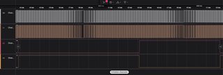
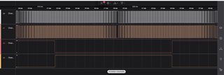
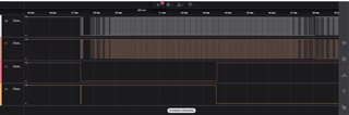
Below are my code and the output of the epwms.
EWPMConfiguration:
    /******************************************************************
     *  Initialization of the  ePWM7 for driving of mosfets
     *  ePWM8 = 20kHz, epwm7 = 50 Hz
     *
     *         epwm8a ->   Q1           epwm7a  ->  Q3
     *
     *
     *         epwm8b  ->  Q2           epwm7b  ->  Q4
     *
     ******************************************************************/


    /******************************************************************
     *  Initialization of the  ePWM8 for driving of transistors mosfets
     *  ePWM7 = 50Hz
     *
     ******************************************************************/

    /**< configuration of the ePWM7 */
    /**< reset peripheral before initialization */
    SysCtl_enablePeripheral(SYSCTL_PERIPH_CLK_EPWM7);

    /**< configuration of the ePWMA */
    /**< reset peripheral before initialization */
    SysCtl_resetPeripheral(SYSCTL_PERIPH_RES_EPWM7);

    SysCtl_setSyncOutputConfig(SYSCTL_SYNC_OUT_SRC_EPWM7SYNCOUT);

    /**< Set up TBCLK */
    EPWM_setTimeBasePeriod(EPWM7_BASE, I_DC2AC_LF_EPWM_PERIOD);          // Set timer period  I_DC2AC_LF_EPWM_PERIOD
    EPWM_setClockPrescaler(EPWM7_BASE, EPWM_CLOCK_DIVIDER_128, EPWM_HSCLOCK_DIVIDER_1);   // TBCLK = EPWMCLK  EPWM_CLOCK_DIVIDER_128
    EPWM_setPhaseShift(EPWM7_BASE, 0U);                             // Set timer phase
    EPWM_setTimeBaseCounter(EPWM7_BASE, 0U);                        // Clear timer counter

    /**< Set up counter mode */
    EPWM_setTimeBaseCounterMode(EPWM7_BASE, EPWM_COUNTER_MODE_UP_DOWN);  // Enable the timer in count up mode
    EPWM_disablePhaseShiftLoad(EPWM7_BASE);                         // Disable phase load

    /**< Set up compare values */
    EPWM_setCounterCompareValue(EPWM7_BASE, EPWM_COUNTER_COMPARE_A, PWM_CMPR_LF_DC2AC(0.4));    // Set PWM duty cycle  PWM_CMPR_LF_DC2AC(0.8)
    EPWM_setCounterCompareValue(EPWM7_BASE, EPWM_COUNTER_COMPARE_B, PWM_CMPR_LF_DC2AC(0.4));    // Set PWM duty cycle PWM_CMPR_DC2DC((0.4(0.5 - 0.4))));

    /**< Set up shadowing */
//    EPWM_setCounterCompareShadowLoadMode(EPWM7_BASE, EPWM_COUNTER_COMPARE_A,
//                                         EPWM_COMP_LOAD_ON_CNTR_ZERO_PERIOD);   // Load on zero or PRD match
//
//    EPWM_setCounterCompareShadowLoadMode(EPWM7_BASE, EPWM_COUNTER_COMPARE_B,
//                                         EPWM_COMP_LOAD_ON_CNTR_ZERO_PERIOD);   // Load on zero or PRD match

    /**< Set up action */
    EPWM_setActionQualifierAction(EPWM7_BASE, EPWM_AQ_OUTPUT_A,
                                  EPWM_AQ_OUTPUT_LOW, EPWM_AQ_OUTPUT_ON_TIMEBASE_ZERO);   // Set pin  on when time base counter = 0
    EPWM_setActionQualifierAction(EPWM7_BASE, EPWM_AQ_OUTPUT_A,
                                  EPWM_AQ_OUTPUT_HIGH, EPWM_AQ_OUTPUT_ON_TIMEBASE_UP_CMPA);  // Set pin low when cmp a up = time base counter
    EPWM_setActionQualifierAction(EPWM7_BASE, EPWM_AQ_OUTPUT_A,
                                  EPWM_AQ_OUTPUT_LOW, EPWM_AQ_OUTPUT_ON_TIMEBASE_DOWN_CMPA);  // Set pin low when cmp a up = time base counter

    EPWM_setActionQualifierAction(EPWM7_BASE, EPWM_AQ_OUTPUT_B,
                                  EPWM_AQ_OUTPUT_HIGH, EPWM_AQ_OUTPUT_ON_TIMEBASE_ZERO);   // Set pin  on when time base counter = 0
    EPWM_setActionQualifierAction(EPWM7_BASE, EPWM_AQ_OUTPUT_B,
                                  EPWM_AQ_OUTPUT_LOW, EPWM_AQ_OUTPUT_ON_TIMEBASE_UP_CMPB);  // Set pin low when cmp a up = time base counter
    EPWM_setActionQualifierAction(EPWM7_BASE, EPWM_AQ_OUTPUT_B,
                                  EPWM_AQ_OUTPUT_HIGH, EPWM_AQ_OUTPUT_ON_TIMEBASE_DOWN_CMPB);  // Set pin low when cmp a up = time base counter

    /**< Set up for synchronization between ePWM */
    EPWM_setSyncOutPulseMode (EPWM7_BASE, EPWM_SYNC_OUT_PULSE_ON_COUNTER_ZERO);   //sync pulse is sent when counter is 0
//    EPWM_setCountModeAfterSync (EPWM7_BASE, EPWM_COUNT_MODE_UP_AFTER_SYNC); //count up for phase shift count after sync
//    EPWM_setPhaseShift (EPWM7_BASE, I_DC2DC_EPWM_PERIOD);   //enable a 180 degree phase shift between both pwm  //TODO not sure
//    EPWM_enablePhaseShiftLoad(EPWM8_BASE);      //enable the phaseshift load to load the phase shift value

    /**< dead band configuration */
    /**< configure RED for delay of xxxms with the b comparator*/
    EPWM_setDeadBandDelayPolarity(EPWM7_BASE, EPWM_DB_FED, EPWM_DB_POLARITY_ACTIVE_LOW);
    EPWM_setDeadBandDelayMode(EPWM7_BASE, EPWM_DB_RED, true);
    EPWM_setRisingEdgeDelayCount(EPWM7_BASE, 20);
    EPWM_setDeadBandDelayMode(EPWM7_BASE, EPWM_DB_FED, true);
    EPWM_setFallingEdgeDelayCount(EPWM7_BASE, 20);

    /****************************************************************************************************
     * configure over epwm trip zone for one time OC protection - TRIP7 and battery current protection - TRIP5
     * trip immediately shuts down th epwm unit
     ******************************************************************************************************/

    //based on comment from next code
    EPWM_disableTripZoneAdvAction(EPWM7_BASE) ;

    EPWM_setTripZoneAction(EPWM7_BASE, EPWM_TZ_ACTION_EVENT_DCAEVT1, EPWM_TZ_ACTION_LOW); //TODO verify

    /**< configure trip zone action for DCAEVT1 and DCBEVT1, trigger when it is high */
    EPWM_setTripZoneDigitalCompareEventCondition (EPWM7_BASE, EPWM_TZ_DC_OUTPUT_A1, EPWM_TZ_EVENT_DCXH_HIGH);

    /**< Configure DCAH and DCBH to use trip7 and trip5 */
    //combine trip7 and trip5
    EPWM_selectDigitalCompareTripInput(EPWM7_BASE, EPWM_DC_TRIP_COMBINATION, EPWM_DC_TYPE_DCAH);

    //trip7
    EPWM_enableDigitalCompareTripCombinationInput(EPWM7_BASE, EPWM_DC_COMBINATIONAL_TRIPIN7, EPWM_DC_TYPE_DCAH);

    //trip5
    EPWM_enableDigitalCompareTripCombinationInput(EPWM7_BASE, EPWM_DC_COMBINATIONAL_TRIPIN5, EPWM_DC_TYPE_DCAH);

    /**< enable trip zone signal for DCAEVT1 and DCBEVT1 and for one short tripping */
    EPWM_enableTripZoneSignals(EPWM7_BASE, EPWM_TZ_SIGNAL_DCAEVT1);

    /**< configure for unfiltered and asynchronous operation */  //TODO verify unfiltered
    EPWM_setDigitalCompareEventSource(EPWM7_BASE, EPWM_DC_MODULE_A, EPWM_DC_EVENT_1,  EPWM_DC_EVENT_SOURCE_ORIG_SIGNAL);

    /**< Set up interrupts */
    EPWM_setInterruptSource(EPWM7_BASE, EPWM_INT_TBCTR_ZERO);

    /**< clear interrupt flag */
    EPWM_clearEventTriggerInterruptFlag(EPWM7_BASE);

    /**< Interrupts that are used are re-mapped to ISR functions found within this file. */
    Interrupt_register(INT_EPWM7, &epwm::ISRDC2ACEPWM7);
    EPWM_enableInterrupt(EPWM7_BASE);


    /******************************************************************
     *  Initialization of the  ePWM7 for driving of transistors mosfets
     *  ePWM8 = 20kHz
     *
     ******************************************************************/

    SysCtl_enablePeripheral(SYSCTL_PERIPH_CLK_EPWM8);
    //asm(" RPT #5 || NOP");

    Interrupt_register(INT_EPWM8, &epwm::ISRDC2ACEPWM8);

    /**< disable peripheral for initialization */
    SysCtl_disablePeripheral(SYSCTL_PERIPH_CLK_TBCLKSYNC); //TODO why

    /**< configuration of the ePWM7 */
    /**< reset peripheral before initialization */
    SysCtl_resetPeripheral(SYSCTL_PERIPH_RES_EPWM8);

    /**< Set up TBCLK */
    EPWM_setTimeBasePeriod(EPWM8_BASE, I_DC2AC_HF_EPWM_PERIOD);          // Set timer period  I_DC2AC_HF_EPWM_PERIOD
    EPWM_setClockPrescaler(EPWM8_BASE, EPWM_CLOCK_DIVIDER_1, EPWM_HSCLOCK_DIVIDER_1);   // TBCLK = EPWMCLK
    EPWM_setPhaseShift(EPWM8_BASE, 0U);                             // Set timer phase
    EPWM_setTimeBaseCounter(EPWM8_BASE, 0U);                        // Clear timer counter

    /**< Set up counter mode */
    EPWM_setTimeBaseCounterMode(EPWM8_BASE, EPWM_COUNTER_MODE_UP_DOWN);  // Enable the timer in count up mode
    EPWM_disablePhaseShiftLoad(EPWM8_BASE);                         // Disable phase load

    /**< Set up compare values */       //TODO not needed
    EPWM_setCounterCompareValue(EPWM8_BASE, EPWM_COUNTER_COMPARE_A, PWM_CMPR_HF_DC2AC(INVERT_DC2AC_STARTUP_DC));    // Set compare value which determines the duty cycle of the PWM_CMPR_HF_DC2AC
    EPWM_setCounterCompareValue(EPWM8_BASE, EPWM_COUNTER_COMPARE_B, PWM_CMPR_HF_DC2AC(INVERT_DC2AC_STARTUP_DC));    // Set compare value which determines the duty cycle of the T2

    /**< Set up shadowing */
//    EPWM_setCounterCompareShadowLoadMode(EPWM8_BASE, EPWM_COUNTER_COMPARE_A,
//                                         EPWM_COMP_LOAD_ON_CNTR_ZERO_PERIOD);   // Load on zero or PRD match
//
//    EPWM_setCounterCompareShadowLoadMode(EPWM8_BASE, EPWM_COUNTER_COMPARE_B,
//                                         EPWM_COMP_LOAD_ON_CNTR_ZERO_PERIOD);   // Load on zero or PRD match


    /**< Set up action qualifier */
    EPWM_setActionQualifierAction(EPWM8_BASE, EPWM_AQ_OUTPUT_A,
                                  EPWM_AQ_OUTPUT_LOW, EPWM_AQ_OUTPUT_ON_TIMEBASE_ZERO);   // Set pin  on when time base counter = 0
    EPWM_setActionQualifierAction(EPWM8_BASE, EPWM_AQ_OUTPUT_A,
                                  EPWM_AQ_OUTPUT_HIGH, EPWM_AQ_OUTPUT_ON_TIMEBASE_UP_CMPA);  // Set pin low when cmp a up = time base counter
    EPWM_setActionQualifierAction(EPWM8_BASE, EPWM_AQ_OUTPUT_A,
                                  EPWM_AQ_OUTPUT_LOW, EPWM_AQ_OUTPUT_ON_TIMEBASE_DOWN_CMPA);  // Set pin low when cmp a up = time base counter

    EPWM_setActionQualifierAction(EPWM8_BASE, EPWM_AQ_OUTPUT_B,
                                  EPWM_AQ_OUTPUT_HIGH, EPWM_AQ_OUTPUT_ON_TIMEBASE_ZERO);   // Set pin  on when time base counter = 0
    EPWM_setActionQualifierAction(EPWM8_BASE, EPWM_AQ_OUTPUT_B,
                                  EPWM_AQ_OUTPUT_LOW, EPWM_AQ_OUTPUT_ON_TIMEBASE_UP_CMPB);  // Set pin low when cmp a up = time base counter
    EPWM_setActionQualifierAction(EPWM8_BASE, EPWM_AQ_OUTPUT_B,
                                  EPWM_AQ_OUTPUT_HIGH, EPWM_AQ_OUTPUT_ON_TIMEBASE_DOWN_CMPB);  // Set pin low when cmp a up = time base counter

    /**< Set up for synchronization between ePWM */
    /**< for start up operation after which it is changed to running mode setting */
    EPWM_setDeadBandDelayPolarity(EPWM8_BASE, EPWM_DB_FED, EPWM_DB_POLARITY_ACTIVE_LOW);
    EPWM_setDeadBandDelayMode(EPWM8_BASE, EPWM_DB_RED, true);
    EPWM_setRisingEdgeDelayCount(EPWM8_BASE, 20);
    EPWM_setDeadBandDelayMode(EPWM8_BASE, EPWM_DB_FED, true);
    EPWM_setFallingEdgeDelayCount(EPWM8_BASE, 20);

    //    EPWM_setPhaseShift (EPWM7_BASE, I_DC2DC_EPWM_PERIOD);   //enable a 180 degree phase shift between both pwm  //TODO not sure
//    EPWM_enablePhaseShiftLoad(EPWM8_BASE);      //enable the phaseshift load to load the phase shift value


    EPWM_setSyncOutPulseMode(EPWM8_BASE,EPWM_SYNC_OUT_PULSE_ON_EPWMxSYNCIN);
    EPWM_setCountModeAfterSync (EPWM8_BASE, EPWM_COUNT_MODE_UP_AFTER_SYNC); //count up for phase shift count after sync
    EPWM_enablePhaseShiftLoad(EPWM8_BASE);      //enable the phaseshift load to load the phase shift value
    EPWM_setPhaseShift (EPWM8_BASE, 0);   //enable a 180 degree phase shift between both pwm  //TODO not sure

    /****************************************************************************************************
     * configure over epwm trip zone for one time OC protection - TRIP7 and battery current protection - TRIP5
     * trip immediately shuts down th epwm unit
     ******************************************************************************************************/

    //based on comment from next code
    EPWM_disableTripZoneAdvAction(EPWM8_BASE) ;

    EPWM_setTripZoneAction(EPWM8_BASE, EPWM_TZ_ACTION_EVENT_DCAEVT1, EPWM_TZ_ACTION_LOW); //TODO verify

    /**< configure trip zone action for DCAEVT1 and DCBEVT1, trigger when it is high */
    EPWM_setTripZoneDigitalCompareEventCondition (EPWM8_BASE, EPWM_TZ_DC_OUTPUT_A1, EPWM_TZ_EVENT_DCXH_HIGH);

    /**< Configure DCAH and DCBH to use trip7 and trip5 */
    //combine trip7 and trip5
    EPWM_selectDigitalCompareTripInput(EPWM8_BASE, EPWM_DC_TRIP_COMBINATION, EPWM_DC_TYPE_DCAH);

    //trip7
    EPWM_enableDigitalCompareTripCombinationInput(EPWM8_BASE, EPWM_DC_COMBINATIONAL_TRIPIN7, EPWM_DC_TYPE_DCAH);

    //trip5
    EPWM_enableDigitalCompareTripCombinationInput(EPWM8_BASE, EPWM_DC_COMBINATIONAL_TRIPIN5, EPWM_DC_TYPE_DCAH);

    /**< enable trip zone signal for DCAEVT1 and DCBEVT1 and for one short tripping */
    EPWM_enableTripZoneSignals(EPWM8_BASE, EPWM_TZ_SIGNAL_DCAEVT1);

    /**< configure for unfiltered and asynchronous operation */  //TODO verify unfiltered
    EPWM_setDigitalCompareEventSource(EPWM8_BASE, EPWM_DC_MODULE_A, EPWM_DC_EVENT_1,  EPWM_DC_EVENT_SOURCE_ORIG_SIGNAL);

    /**< Set up interrupts */
    /**< Interrupts that are used are re-mapped to ISR functions found within this file. */

    EPWM_enableInterrupt(EPWM8_BASE);
    EPWM_setInterruptSource(EPWM8_BASE, EPWM_INT_TBCTR_ZERO);
    EPWM_setInterruptEventCount(EPWM8_BASE, 1U);

    /**< clear interrupt flag */
    EPWM_clearEventTriggerInterruptFlag(EPWM8_BASE);


    /**< enable peripheral for initialization */
    SysCtl_enablePeripheral(SYSCTL_PERIPH_CLK_TBCLKSYNC);

    Interrupt_enable(INT_EPWM7);
    Interrupt_enable(INT_EPWM8);
CLA Setup:
    SysCtl_enablePeripheral(SYSCTL_PERIPH_CLK_CLA1);
    asm(" RPT #5 || NOP");
#ifdef _FLASH
    memcpy((uint32_t *)&Cla1ProgRunStart, (uint32_t *)&Cla1ProgLoadStart, (uint32_t)&Cla1ProgLoadSize);     // Copy the CLA program code from its load address to the CLA program
#endif

    //Perform RAM initialization on the message RAMs
    MemCfg_initSections(MEMCFG_SECT_MSGX_ALL);
    while(MemCfg_getInitStatus(MEMCFG_SECT_MSGX_ALL) == false)
    {
    }

    /**< Shared between the CPU and the CLA */
    //MemCfg_setLSRAMMasterSel(MEMCFG_SECT_LS2, MEMCFG_LSRAMMASTER_CPU_CLA1);

    MemCfg_setLSRAMMasterSel(MEMCFG_SECT_LS4, MEMCFG_LSRAMMASTER_CPU_CLA1);     //Cla1Prog
    MemCfg_setCLAMemType(MEMCFG_SECT_LS4, MEMCFG_CLA_MEM_PROGRAM);

    MemCfg_setLSRAMMasterSel(MEMCFG_SECT_LS3, MEMCFG_LSRAMMASTER_CPU_CLA1);     //CLA1mathTables
    MemCfg_setCLAMemType(MEMCFG_SECT_LS3, MEMCFG_CLA_MEM_DATA);

    MemCfg_setLSRAMMasterSel(MEMCFG_SECT_LS5, MEMCFG_LSRAMMASTER_CPU_CLA1);     //scratchpad
    MemCfg_setCLAMemType(MEMCFG_SECT_LS5, MEMCFG_CLA_MEM_DATA);


    /**< Memory configuration for CLA data or CLA programme memory */
    //MemCfg_setCLAMemType(MEMCFG_SECT_LS2, MEMCFG_CLA_MEM_DATA);


#pragma diag_suppress=770
    CLA_mapTaskVector(CLA1_BASE, CLA_MVECT_1, (uint16_t)&Cla1Task1);
    CLA_mapTaskVector(CLA1_BASE, CLA_MVECT_2, (uint16_t)&Cla1Task2);
    CLA_mapTaskVector(CLA1_BASE, CLA_MVECT_3, (uint16_t)&Cla1Task3);
    CLA_mapTaskVector(CLA1_BASE, CLA_MVECT_4, (uint16_t)&Cla1Task4);
    CLA_mapTaskVector(CLA1_BASE, CLA_MVECT_5, (uint16_t)&Cla1Task5);
    CLA_mapTaskVector(CLA1_BASE, CLA_MVECT_8, (uint16_t)&Cla1Task8);
#pragma diag_warning=770

    /**< select trigger source */
    CLA_setTriggerSource(CLA_TASK_1, CLA_TRIGGER_EPWM8INT);
    CLA_setTriggerSource(CLA_TASK_2, CLA_TRIGGER_ADCB1);
    //CLA_setTriggerSource(CLA_TASK_3, CLA_TRIGGER_ADCB1);
    CLA_setTriggerSource(CLA_TASK_4, CLA_TRIGGER_SOFTWARE);

    /**< Map interrupt routines to interrupts */
    //Interrupt_register(INT_CLA1_1, &Cla1Task1ISR);      //TODO is it needed
    /**< Disable background task */
    CLA_disableBackgroundTask(CLA1_BASE);
CLA task:
static inline void CLATask1DC2ACCalculation(void)
{
    s_cla_cal._20khz_counter++;

//        s_cla_cal._20khz_counter = 0;

        RAMPGEN_ *p = &ramp_gen;

        // Compute the angle rate
        s_cla_cal.ramp_gen_out += (p->stepAngleMax*p->freq);

        // Saturate the angle rate within (0,1)
//        if (s_cla_cal.ramp_gen_out > (1.0f))
//        {
//            s_cla_cal.ramp_gen_out -= (1.0f);
//        }
        ramp_gen.out = s_cla_cal.ramp_gen_out;
//        new_dc2ac_dc = s_cla_cal.ramp_gen_out;

        s_cla_cal.sin_result = CLAsin(s_cla_cal.ramp_gen_out*6.283185307f);
        s_c28_cal.modu_index = 0.5;

        //do zero crossing calculation
        if (s_cla_cal.sin_result <= (float32_t)(0.00) && s_cla_cal.sin_result_prev > (float32_t)(0.00))
        {
            s_cla_cal.abc = 1;
        }

        if(s_cla_cal.abc)
        {
            s_inv_ccl_var.new_dc = s_c28_cal.modu_index * s_cla_cal.sin_result;
            new_dc2ac_dc = 1 + s_inv_ccl_var.new_dc;
            if (s_cla_cal.sin_result > (float32_t)(0.00) && s_cla_cal.sin_result_prev >= (float32_t)(0.00))
            {
                s_cla_cal.abc = 0;
            }
        }
        else
        {
            new_dc2ac_dc = s_c28_cal.modu_index * s_cla_cal.sin_result;
        }
        s_cla_cal.sin_result_prev = s_cla_cal.sin_result;
//        new_dc2ac_dc = s_cla_cal.sin_result;
//        s_inv_ccl_var.new_dc = s_c28_cal.modu_index * s_cla_cal.sin_result;

        if(s_cla_cal._20khz_counter == 20000)
        {
            s_cla_cal._20khz_counter = 0;
            s_cla_cal.ramp_gen_out = 0;
//            s_cla_cal.xyz = 0;
        }
        //un tested
        //s_inv_ccl_var.ccl_cont_signal_output = DCL_runPI_L1(&cla_con_inv_ccl_pi_para, s_inv_ccl_var.vcl_iac_ref_norm, s_inv_ccl_var.rec_curr_norm);

    }
ePWM8 ISR:
__interrupt void epwm::ISRDC2ACEPWM8(void)
{
    EPWM_setCounterCompareValue(EPWM8_BASE, EPWM_COUNTER_COMPARE_A, PWM_CMPR_HF_DC2AC(new_dc2ac_dc));    // Set compare value which determines the duty cycle of the PWM_CMPR_HF_DC2AC
    EPWM_setCounterCompareValue(EPWM8_BASE, EPWM_COUNTER_COMPARE_B, PWM_CMPR_HF_DC2AC(new_dc2ac_dc));    // Set compare value which determines the duty cycle of the T2

    /**< clear interrupt flag */
//    EPWM_clearEventTriggerInterruptFlag(EPWM8_BASE);
    EPwm8Regs.ETCLR.bit.INT = 1;
    /**< Acknowledge interrupt group */
    PieCtrlRegs.PIEACK.all = PIEACK_GROUP3;
}
The epwm output:
I have carefully gone through the c2000 reference manual, followed all instructions and still didn’t get the desired output.
Please help.

