This thread has been locked.

If you have a related question, please click the "Ask a related question" button in the top right corner. The newly created question will be automatically linked to this question.

TMS320F28386S: CPU startup conditions (power sequence)

Expert 2590 points
Part Number: TMS320F28386S

Hi All,

I have a question regarding the CPU boot sequence.
I am trying to follow the power sequence in the datasheet,
but CPU does not boot.

The following is a description of the conditions we have followed.
Please let us know the cause of CPU not booting.

<Conditions under which the CPU does not start up>

・VDD (1.2V) is started up about 200ms after VDDIO (3.3V) is started up.
(External reset release is released approximately 70ms after VDDIO start-up.)
・VDD(1.2V) was started up about 509ms after VDDIO(3.3V) was started up.
(External reset release is released approximately 70ms after VDDIO start-up.)
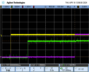
・VDD(1.2V) was started up about 642ms after VDDIO(3.3V) was started up.
(External reset release is released approximately 70ms after VDDIO start-up.)
・VDD(1.2V) was started up about 832ms after VDDIO(3.3V) was started up.
(External reset release is released approximately 70ms after VDDIO start-up.)

<CPU startup conditions>

・VDD(1.2V) was started up about 910ms after VDDIO(3.3V) was started up.
(External reset release is released approximately 70 ms after VDDIO startup.)
・VDD(1.2V) was started up about 1.2s after VDDIO(3.3V) was started up.
(External reset release is released approximately 70ms after VDDIO start-up.)
・When started up at a slower time than the above, it will start up at any time.
(External reset release is released approximately 70ms after VDDIO startup.)
・After starting up VDDIO (3.3V), VDD (1.2V) is started up about 200ms later,
External reset is released after approx. 1.5ms.
・The device will also start up at a slower external reset release time than the above.

  • Please refer to Figure 7-5. Power Up/Down Sequence in page 103 of www.ti.com/lit/SPRSP14. XRS is released only after VDDIO and VDD have stabilized. Please provide the schematics of the circuitry connected to the -XRS pin. Also provide the waveform of VDDIO, VDD and -XRS pins during power-up.

  • Hi Hareesh,

    Thank you for your reply

    Please wait to provide schematics and waveforms as this is a customer question.

    1, VDDIO(3.3V) was started up, and 200ms later, VDD(1.2V) was started up.
    2, When VDDIO(3.3V) was started up and the XRSn was released less than 800ms later, the CPU did not start up.
    3, When VDDIO(3.3V) was started up and the XRSn was released in more than 900ms,the CPU started up.

    In other words, the CPU does not boot up in the order of VDDIO,VDD, and XRSn.

    I think I meet the Operating Conditions and Characteristics, but what is the problem?

    Best Regards,

    Ito

  • Ito-san,

         Unless you provide the -XRS pin circuit and the waveforms for both passing and failing condition, it is hard for me to provide an answer.

  • Hi Hareesh,

    Thank you for your reply

    Waveforms of power supply to CPU at startup are attached.

    1CH (yellow): 3. 3V
    2CH (green): 1.2V
    3CH (purple): External reset input signal

    1,
    1.2V rises approximately 200ms after 3.3V rises,
    After about 530ms after that, when an external reset is input,
    CPU does not seem to start up normally.

    2,
    1.2V rises approximately 200ms after 3.3V rises,
    After about 700ms or later, the CPU is not responding properly.
    CPU seems to start up normally when external reset is input.
    When an external reset is input, the CPU starts normally.

    What is the cause of not starting up under condition 1?

     Best Regards,

    Ito

  • Ito,

              You have not attached the schematics of the reset pin, as I had requested earlier. Ideally, I would like to see the connections to all the MCU pins. Specifically, I  would like see the power-supply, -XRS and boot-mode-select pins.

    After about 530ms after that, when an external reset is input,

    530ms is way too long a time to release reset. It is almost half-a-second. This, in itself, is not a problem but I am wondering if it points to something I am missing.

    What is the cause of not starting up under condition 1?

    You have not provided me enough information to suggest areas to look. The problem is external to our MCU.

  • Hi Hareesh,

    I sent you the schematic to private message.
    Please check it.

    >>530ms is way too long a time to release reset.

    Why is 530ms too slow?

    Also, please tell me exactly how long a delay is needed to start up.


    Best Regards 

    Ito

  • Ito,

          I have provided my feedback about the design in a private message. 

  • Hi Hareesh,

    I just checked with the customer,
    XRS signal is written as TRST,
    There seems to be no problem.
    Are there any other factors?
    If there is no information on the rise time delay,
    If you have no information about the rise time delay, please ask a professional engineer.

    Best Regards,

    Ito

  • Ito,        

                    The circuit sent in the Excel spreadsheet is misleading. There is a block titled “reset circuit” but it appears it has nothing to do with generating a reset. Rather, it looks like the JTAG circuit. Also, the schematics has been sent in bits and pieces (and without any component part numbers). The PDF file has a signal called “RES#” but there is no information where this signal is coming from. Due to all these, no meaningful analysis of the circuit is possible. I regret I cannot help further.