This thread has been locked.

If you have a related question, please click the "Ask a related question" button in the top right corner. The newly created question will be automatically linked to this question.

PMP23126: Zero load transformer current

Part Number: PMP23126
Other Parts Discussed in Thread: C2000WARE

In the software design document, zero load stability results are shown as,

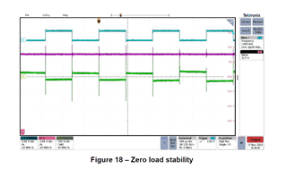
Fig. 18 gives the switching waveform and the output voltage. The switching frequency will settle at around 1kHz at zero load.CH2 is Leg1 HS switching waveform, CH 3 is the output voltage, and CH4 is the transformer current.

(C:\ti\c2000\C2000Ware_DigitalPower_SDK_5_01_00_00\solutions\pmp23126\source\psfbpcmc\include)

I couldn't understand the transformer waveform is in square nature. Because in other test cases it shown as triangular type. In test report TIDT275 also the transformer current is kind on triangular.

Can any one help me on this?

  • Hi Keval,

    During normal operation, the triangular portion of the XFMR current comes from when a diagonal pair of primary side FETs are on at the same time. The flat portion of the current comes from the free-wheeling time where either both high sides or both low sides are on. 

    In frequency reduction mode, a minimum amount of time for overlap of diagonal pairs is maintained but because we are reducing the switching frequency, the free-wheeling time is extended. This is what you are seeing in the waveform at no load. If we were to zoom in where the XFMR current is changing polarity, we would see the triangular portion of the current.

    Best Regards,

    Ben Lough

  • Thanks for explanation.