This thread has been locked.

If you have a related question, please click the "Ask a related question" button in the top right corner. The newly created question will be automatically linked to this question.

TMS320F28388D: TMS320F28388D, input signal processing

Part Number: TMS320F28388D
Other Parts Discussed in Thread: SYSCONFIG

Hello,
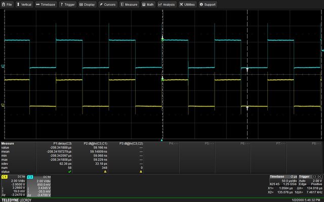
I would like to do the following: I have an input pwm signal with some frequency (about 10 kHz) on one of the pins of TMS320F28388D and

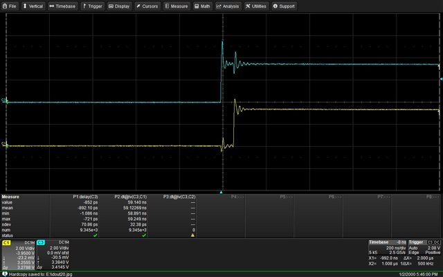
I would like to get the same output pwm signal on other pin in which the rising edge of the input signals should be delayed from 5 ns to 50 ns,

and the falling edge of the output signal must coincide with the falling edge of the input signal.

The input and output signal must be synchronized, but the output signal has a shift of 5 ns to 50 ns on the rising edge.

How to do this on TMS320F28388D?

Thanks.

Alex

  • Hi Alex,

    Can you specify how you are using this 10kHz PWM as an input? Are you generating this signal on the F2838x device and wanting to physically route it as an input (e.g. to an INPUT XBAR pin) and try to use this as an external syncing source for the sync source of another PWM? Or do you mean you are wanting to use the internal EPWM hardware to associate the two?

    From what I've gleaned from your explanation, it seems like you can just use a single instance of PWM on F2838x to generate your EPWM signals (let's use EPWM1A and EPWM1B, for example). You can generate a 10kHz PWM signal for both channels (A and B) and then just use the deadband module to add rising edge delay on one channel with respect to the other. In this way, the signals are synced, but there is configurable rising edge delay on one of the channels.

    To explain some of the calculations (if that is the source of confusion):

    • If you have a time-base clock (TBCLK) frequency 100MHz, this means that each TBCLK period = 1ns.
    • To have your 10kHz PWN frequency, if (for example) you were using up-count:
      • TBPRD = (FTBCLK/FPWM) -1 = (100MHz/ 10kHz) -1 = 9999
    • Then, you can implement a rising edge delay (RED) on only one channel (using the deadband module)
      • e.g. "Mode 7" from the device TRM deadband section:
      • The TRM also explains that rising edge delay (RED) is equal to the DBRED register value multiplied by T_TBCLK:
        • RED = DBRED x T_TBCLK,       where T_TBCLK is the period of TBCLK (the prescaled version of EPWMCLK)
        • This means that a DBRED of 5 is equivalent to 5 TBCLK period which would be 5ns
        • So to have a rising edge delay of 5-50 ns, you would apply a DBRED of 5-50. 

    Best Regards,

    Allison

  • Hello Allison,

    thank you for your reply.

    The input PWM signal is external signal from other clock source. The frequency of the input signal can be variable from 10kHz up to 50kHz.

    Is it possible to connect the input signal direct to deadband module?

    Is it possible to use input signal as trigger for starting of the timer without interrupt?

     Thanks.

    Best regards,

    Alex

  • Hi Alex,

    My initial thoughts are to perhaps use clock signal input to the EPWM digital compare module as a sync source for the EPWM. From there, you could still apply a rising edge delay to the signal. To turn off the PWM at the same time, you could use the signal to generate a trip signal, so that when the input goes low, you configure the EPWM to trip low. 

    But let me also discuss this with other PWM experts when we are back in office next week and let you know further input on this.

    Best Regards,

    Allison

  • Hello Allison,

    thank you for your reply.

    Best Regards,

    Alex

  • Hi Alex,

    Ok I discussed with another colleague and believe this should be achievable. 

    Essentially, your PWM counter would always be counting up, but you would use the clock source as an external sync source (EXTSYNCIN) to reset the PWM to '0' every time the clock signal goes high. You would have an action qualifier on CTR=0 to set the PWM high as well, and need to be sure that your TBPRD will always be bigger than the clock's period for this since we want it to always be counting up and not stop/decrement. 

    You can also add your rising edge delay (RED) on top of this.

    To set the PWM low, you would definitely have to use a T1 event in the Action Qualifier module with an action set up on 'T1' to clear the PWM output low. If you wanted a more immediate shut-off, you can also use the clock as an input to the trip zone for a cycle-by-cycle trip. Since trip signals are "active-low", when the clock goes low, the PWM would also be tripped low. 

    The reason you have to use T1 as well is because of the rising edge delay (RED). The RED in the deadband module depends on the actions specified in the Action Qualifier module. If there is no direct 'action' setting the PWM low (if, for example, you are only using trip zone to shut off PWM), the deadband will not recognize the rising edge on '0' as a legitimate rising edge, and will thus not apply the deadband RED. 

    Let me know your thoughts/if you are able to try this configuration.

    Best Regards,

    Allison

  • Hello Allison,

    Thank you very much for your help and advice.

    Next week I will try to implement my task and tell you about my result.

    Best regards,

    Alex

  • Sounds good, Alex. I will await your update.

    Best Regards,

    Allison

  • Hello Allison,

    I have a good result. I used one PMW signal (blue signal) as input extenal signal. GPIO30 is input for this signal.

    Using inputxbar I did XBAR_INPUT5 as Sync-in source for PWM1

    and XBAR_INPUT1 for Trip Zone (Trip1)

    Yellow signal is the result of processing the input signal.

    Blue signal is external input signal, yellow signal is PWM signal

    This is a timer configuration for signal processing.

    I used DCAEVT1 for T1 trigger and DCAEVT2 for T2 trigger in order to detect a rising edge and a falling edge of the input signal.

    When I have a T1 event  I set an output pins to high.

    When I have a T2 event  I set an output pins to low.

    Trip1 is used in order to detect a rising edge and a falling edge of the input signal.

    But I have some problems.

    EPWM Dead-Band is not work.

    Could you check my EPWM configuration and help me to activate the EPWM Dead-Band?

    Currently the delay between the rising edge of the external signal and the output signal is about 59 ns and is independent of the EPWM deadband,

    although I used it.

    Thank you for your support.

    Best regards,

    Alex

  • Hi Alex,

    Glad to see the progress! To clarify, are you using Trip 1 to set the PWM both high and low? Or just low? And using the external sync to set it high?

    The trip zone is the last submodule in the flow of EPWM signal generation, so if you use the Trip zone at all, it will override other EPWM settings (such as an action qualifier). This is critical as a safety feature, but can also mean that you are accidentally masking other configurations such as deadband.

    Also, instead of attaching images, could you please insert the SysConfig code ("Insert" button and then "</> Code" selection here in E2E) or attach your SysConfig file? This way I can easily take a look at the configurations and try things out myself Slight smile

    Best Regards,

    Allison

  • Hello Allison,

    I changed my code a little.

    I use a clock pulse to start the timer and CMPA to do some delay for rising edge and in order to control the falling edge I use Trip1 for the TZ1 event.

    It works, but I have one extra short pulse.

    How can I avoid this short impulse?

    I attached my code for EPWM and two pictures.

    //*****************************************************************************
    //
    // EPWM Configurations
    //
    //*****************************************************************************
    void EPWM_init()
    {
        EPWM_setClockPrescaler(myEPWM1_BASE, EPWM_CLOCK_DIVIDER_1, EPWM_HSCLOCK_DIVIDER_1);	
        EPWM_setTimeBasePeriod(myEPWM1_BASE, 6000);	
        EPWM_setTimeBaseCounter(myEPWM1_BASE, 0);	
        EPWM_setTimeBaseCounterMode(myEPWM1_BASE, EPWM_COUNTER_MODE_UP);	
        EPWM_enablePhaseShiftLoad(myEPWM1_BASE);	
        EPWM_setPhaseShift(myEPWM1_BASE, 0);	
        EPWM_setSyncInPulseSource(myEPWM1_BASE, EPWM_SYNC_IN_PULSE_SRC_INPUTXBAR_OUT5);	
        EPWM_setCounterCompareValue(myEPWM1_BASE, EPWM_COUNTER_COMPARE_A, 200);	
        EPWM_disableCounterCompareShadowLoadMode(myEPWM1_BASE, EPWM_COUNTER_COMPARE_A);	
        EPWM_setCounterCompareShadowLoadMode(myEPWM1_BASE, EPWM_COUNTER_COMPARE_A, EPWM_COMP_LOAD_ON_CNTR_ZERO);	
        EPWM_setCounterCompareValue(myEPWM1_BASE, EPWM_COUNTER_COMPARE_B, 0);	
        EPWM_disableCounterCompareShadowLoadMode(myEPWM1_BASE, EPWM_COUNTER_COMPARE_B);	
        EPWM_setCounterCompareShadowLoadMode(myEPWM1_BASE, EPWM_COUNTER_COMPARE_B, EPWM_COMP_LOAD_ON_CNTR_ZERO);	
        EPWM_setActionQualifierT2TriggerSource(myEPWM1_BASE, EPWM_AQ_TRIGGER_EVENT_TRIG_DCA_2);	
        EPWM_setActionQualifierAction(myEPWM1_BASE, EPWM_AQ_OUTPUT_A, EPWM_AQ_OUTPUT_LOW, EPWM_AQ_OUTPUT_ON_TIMEBASE_ZERO);	
        EPWM_setActionQualifierAction(myEPWM1_BASE, EPWM_AQ_OUTPUT_A, EPWM_AQ_OUTPUT_NO_CHANGE, EPWM_AQ_OUTPUT_ON_TIMEBASE_PERIOD);	
        EPWM_setActionQualifierAction(myEPWM1_BASE, EPWM_AQ_OUTPUT_A, EPWM_AQ_OUTPUT_HIGH, EPWM_AQ_OUTPUT_ON_TIMEBASE_UP_CMPA);	
        EPWM_setActionQualifierAction(myEPWM1_BASE, EPWM_AQ_OUTPUT_A, EPWM_AQ_OUTPUT_NO_CHANGE, EPWM_AQ_OUTPUT_ON_TIMEBASE_DOWN_CMPA);	
        EPWM_setActionQualifierAction(myEPWM1_BASE, EPWM_AQ_OUTPUT_A, EPWM_AQ_OUTPUT_NO_CHANGE, EPWM_AQ_OUTPUT_ON_TIMEBASE_UP_CMPB);	
        EPWM_setActionQualifierAction(myEPWM1_BASE, EPWM_AQ_OUTPUT_A, EPWM_AQ_OUTPUT_NO_CHANGE, EPWM_AQ_OUTPUT_ON_TIMEBASE_DOWN_CMPB);	
        EPWM_setActionQualifierShadowLoadMode(myEPWM1_BASE, EPWM_ACTION_QUALIFIER_B, EPWM_AQ_LOAD_ON_SYNC_ONLY);	
        EPWM_setActionQualifierAction(myEPWM1_BASE, EPWM_AQ_OUTPUT_B, EPWM_AQ_OUTPUT_NO_CHANGE, EPWM_AQ_OUTPUT_ON_TIMEBASE_ZERO);	
        EPWM_setActionQualifierAction(myEPWM1_BASE, EPWM_AQ_OUTPUT_B, EPWM_AQ_OUTPUT_NO_CHANGE, EPWM_AQ_OUTPUT_ON_TIMEBASE_PERIOD);	
        EPWM_setActionQualifierAction(myEPWM1_BASE, EPWM_AQ_OUTPUT_B, EPWM_AQ_OUTPUT_NO_CHANGE, EPWM_AQ_OUTPUT_ON_TIMEBASE_UP_CMPA);	
        EPWM_setActionQualifierAction(myEPWM1_BASE, EPWM_AQ_OUTPUT_B, EPWM_AQ_OUTPUT_NO_CHANGE, EPWM_AQ_OUTPUT_ON_TIMEBASE_DOWN_CMPA);	
        EPWM_setActionQualifierAction(myEPWM1_BASE, EPWM_AQ_OUTPUT_B, EPWM_AQ_OUTPUT_NO_CHANGE, EPWM_AQ_OUTPUT_ON_TIMEBASE_UP_CMPB);	
        EPWM_setActionQualifierAction(myEPWM1_BASE, EPWM_AQ_OUTPUT_B, EPWM_AQ_OUTPUT_NO_CHANGE, EPWM_AQ_OUTPUT_ON_TIMEBASE_DOWN_CMPB);	
        EPWM_setActionQualifierAction(myEPWM1_BASE, EPWM_AQ_OUTPUT_B, EPWM_AQ_OUTPUT_LOW, EPWM_AQ_OUTPUT_ON_T1_COUNT_UP);	
        EPWM_setRisingEdgeDelayCountShadowLoadMode(myEPWM1_BASE, EPWM_RED_LOAD_ON_CNTR_ZERO);	
        EPWM_setRisingEdgeDelayCount(myEPWM1_BASE, 400);	
        EPWM_setFallingEdgeDelayCountShadowLoadMode(myEPWM1_BASE, EPWM_FED_LOAD_ON_CNTR_ZERO);	
        EPWM_setFallingEdgeDelayCount(myEPWM1_BASE, 400);	
        EPWM_disableRisingEdgeDelayCountShadowLoadMode(myEPWM1_BASE);	
        EPWM_disableFallingEdgeDelayCountShadowLoadMode(myEPWM1_BASE);	
        EPWM_setTripZoneAction(myEPWM1_BASE, EPWM_TZ_ACTION_EVENT_TZA, EPWM_TZ_ACTION_LOW);	
        EPWM_setTripZoneAction(myEPWM1_BASE, EPWM_TZ_ACTION_EVENT_DCAEVT1, EPWM_TZ_ACTION_DISABLE);	
        EPWM_setTripZoneAction(myEPWM1_BASE, EPWM_TZ_ACTION_EVENT_DCAEVT2, EPWM_TZ_ACTION_DISABLE);	
        EPWM_enableTripZoneSignals(myEPWM1_BASE, EPWM_TZ_SIGNAL_CBC1);	
        EPWM_setTripZoneDigitalCompareEventCondition(myEPWM1_BASE, EPWM_TZ_DC_OUTPUT_A1, EPWM_TZ_EVENT_DCXH_HIGH);	
        EPWM_setTripZoneDigitalCompareEventCondition(myEPWM1_BASE, EPWM_TZ_DC_OUTPUT_A2, EPWM_TZ_EVENT_DCXH_LOW);	
        EPWM_setDigitalCompareEventSyncMode(myEPWM1_BASE, EPWM_DC_MODULE_A, EPWM_DC_EVENT_1, EPWM_DC_EVENT_INPUT_NOT_SYNCED);	
        EPWM_setDigitalCompareEventSyncMode(myEPWM1_BASE, EPWM_DC_MODULE_A, EPWM_DC_EVENT_2, EPWM_DC_EVENT_INPUT_NOT_SYNCED);	
        EPWM_setTripZoneDigitalCompareEventCondition(myEPWM1_BASE, EPWM_TZ_DC_OUTPUT_B1, EPWM_TZ_EVENT_DCXH_LOW);	
        EPWM_setClockPrescaler(myEPWM2_BASE, EPWM_CLOCK_DIVIDER_1, EPWM_HSCLOCK_DIVIDER_1);	
        EPWM_setTimeBasePeriod(myEPWM2_BASE, 10000);	
        EPWM_setTimeBaseCounter(myEPWM2_BASE, 0);	
        EPWM_setTimeBaseCounterMode(myEPWM2_BASE, EPWM_COUNTER_MODE_UP);	
        EPWM_disablePhaseShiftLoad(myEPWM2_BASE);	
        EPWM_setPhaseShift(myEPWM2_BASE, 0);	
        EPWM_setSyncInPulseSource(myEPWM2_BASE, EPWM_SYNC_IN_PULSE_SRC_SYNCOUT_EPWM2);	
        EPWM_setCounterCompareValue(myEPWM2_BASE, EPWM_COUNTER_COMPARE_A, 5000);	
        EPWM_setCounterCompareShadowLoadMode(myEPWM2_BASE, EPWM_COUNTER_COMPARE_A, EPWM_COMP_LOAD_ON_CNTR_ZERO);	
        EPWM_setCounterCompareValue(myEPWM2_BASE, EPWM_COUNTER_COMPARE_B, 0);	
        EPWM_setCounterCompareShadowLoadMode(myEPWM2_BASE, EPWM_COUNTER_COMPARE_B, EPWM_COMP_LOAD_ON_CNTR_ZERO);	
        EPWM_setActionQualifierAction(myEPWM2_BASE, EPWM_AQ_OUTPUT_A, EPWM_AQ_OUTPUT_HIGH, EPWM_AQ_OUTPUT_ON_TIMEBASE_ZERO);	
        EPWM_setActionQualifierAction(myEPWM2_BASE, EPWM_AQ_OUTPUT_A, EPWM_AQ_OUTPUT_NO_CHANGE, EPWM_AQ_OUTPUT_ON_TIMEBASE_PERIOD);	
        EPWM_setActionQualifierAction(myEPWM2_BASE, EPWM_AQ_OUTPUT_A, EPWM_AQ_OUTPUT_LOW, EPWM_AQ_OUTPUT_ON_TIMEBASE_UP_CMPA);	
        EPWM_setActionQualifierAction(myEPWM2_BASE, EPWM_AQ_OUTPUT_A, EPWM_AQ_OUTPUT_NO_CHANGE, EPWM_AQ_OUTPUT_ON_TIMEBASE_DOWN_CMPA);	
        EPWM_setActionQualifierAction(myEPWM2_BASE, EPWM_AQ_OUTPUT_A, EPWM_AQ_OUTPUT_NO_CHANGE, EPWM_AQ_OUTPUT_ON_TIMEBASE_UP_CMPB);	
        EPWM_setActionQualifierAction(myEPWM2_BASE, EPWM_AQ_OUTPUT_A, EPWM_AQ_OUTPUT_NO_CHANGE, EPWM_AQ_OUTPUT_ON_TIMEBASE_DOWN_CMPB);	
        EPWM_setActionQualifierAction(myEPWM2_BASE, EPWM_AQ_OUTPUT_B, EPWM_AQ_OUTPUT_NO_CHANGE, EPWM_AQ_OUTPUT_ON_TIMEBASE_ZERO);	
        EPWM_setActionQualifierAction(myEPWM2_BASE, EPWM_AQ_OUTPUT_B, EPWM_AQ_OUTPUT_NO_CHANGE, EPWM_AQ_OUTPUT_ON_TIMEBASE_PERIOD);	
        EPWM_setActionQualifierAction(myEPWM2_BASE, EPWM_AQ_OUTPUT_B, EPWM_AQ_OUTPUT_NO_CHANGE, EPWM_AQ_OUTPUT_ON_TIMEBASE_UP_CMPA);	
        EPWM_setActionQualifierAction(myEPWM2_BASE, EPWM_AQ_OUTPUT_B, EPWM_AQ_OUTPUT_NO_CHANGE, EPWM_AQ_OUTPUT_ON_TIMEBASE_DOWN_CMPA);	
        EPWM_setActionQualifierAction(myEPWM2_BASE, EPWM_AQ_OUTPUT_B, EPWM_AQ_OUTPUT_NO_CHANGE, EPWM_AQ_OUTPUT_ON_TIMEBASE_UP_CMPB);	
        EPWM_setActionQualifierAction(myEPWM2_BASE, EPWM_AQ_OUTPUT_B, EPWM_AQ_OUTPUT_NO_CHANGE, EPWM_AQ_OUTPUT_ON_TIMEBASE_DOWN_CMPB);	
        EPWM_setRisingEdgeDelayCountShadowLoadMode(myEPWM2_BASE, EPWM_RED_LOAD_ON_CNTR_ZERO);	
        EPWM_setFallingEdgeDelayCountShadowLoadMode(myEPWM2_BASE, EPWM_FED_LOAD_ON_CNTR_ZERO);	
        EPWM_disableRisingEdgeDelayCountShadowLoadMode(myEPWM2_BASE);	
        EPWM_disableFallingEdgeDelayCountShadowLoadMode(myEPWM2_BASE);	
    }


    EPWM2 is used as external clock pulse (blue signal) for EPWM1 (yellow signal).

    it is a syscfg file 

    /**
     * These arguments were used when this file was generated. They will be automatically applied on subsequent loads
     * via the GUI or CLI. Run CLI with '--help' for additional information on how to override these arguments.
     * @cliArgs --device "F28003x" --package "100PZ" --part "F28003x_100PZ" --context "system" --product "C2000WARE@5.00.00.00"
     * @versions {"tool":"1.19.0+3426"}
     */
    
    /**
     * Import the modules used in this configuration.
     */
    const epwm             = scripting.addModule("/driverlib/epwm.js", {}, false);
    const epwm1            = epwm.addInstance();
    const epwm2            = epwm.addInstance();
    const gpio             = scripting.addModule("/driverlib/gpio.js", {}, false);
    const gpio1            = gpio.addInstance();
    const inputxbar        = scripting.addModule("/driverlib/inputxbar.js", {}, false);
    const inputxbar1       = inputxbar.addInstance();
    const inputxbar_input  = scripting.addModule("/driverlib/inputxbar_input.js");
    const inputxbar_input1 = inputxbar_input.addInstance();
    const inputxbar_input2 = inputxbar_input.addInstance();
    const sync             = scripting.addModule("/driverlib/sync.js");
    
    /**
     * Write custom configuration values to the imported modules.
     */
    epwm1.$name                                                         = "myEPWM1";
    epwm1.epwmTimebase_hsClockDiv                                       = "EPWM_HSCLOCK_DIVIDER_1";
    epwm1.epwmDeadband_delayFED                                         = 400;
    epwm1.epwmActionQualifier_EPWM_AQ_OUTPUT_B_shadowMode               = true;
    epwm1.epwmActionQualifier_EPWM_AQ_OUTPUT_B_shadowEvent              = "EPWM_AQ_LOAD_ON_SYNC_ONLY";
    epwm1.epwmDigitalCompare_EPWM_TZ_DC_OUTPUT_B1                       = "EPWM_TZ_EVENT_DCXH_LOW";
    epwm1.epwmActionQualifier_EPWM_AQ_OUTPUT_B_ON_T1_COUNT_UP           = "EPWM_AQ_OUTPUT_LOW";
    epwm1.epwmTimebase_syncInPulseSource                                = "EPWM_SYNC_IN_PULSE_SRC_INPUTXBAR_OUT5";
    epwm1.epwmTimebase_periodLoadEvent                                  = "EPWM_SHADOW_LOAD_MODE_SYNC";
    epwm1.epwmTimebase_period                                           = 6000;
    epwm1.epwmCounterCompare_enableShadowLoadModeCMPB                   = false;
    epwm1.epwmCounterCompare_enableShadowLoadModeCMPA                   = false;
    epwm1.epwmTimebase_counterMode                                      = "EPWM_COUNTER_MODE_UP";
    epwm1.epwmTripZone_EPWM_TZ_ACTION_EVENT_DCAEVT1                     = "EPWM_TZ_ACTION_DISABLE";
    epwm1.epwmDeadband_delayRED                                         = 400;
    epwm1.epwmTripZone_EPWM_TZ_ACTION_EVENT_DCAEVT2                     = "EPWM_TZ_ACTION_DISABLE";
    epwm1.epwmDigitalCompare_EPWM_DC_MODULE_A_EPWM_DC_EVENT_1_eventSync = "EPWM_DC_EVENT_INPUT_NOT_SYNCED";
    epwm1.epwmDigitalCompare_EPWM_DC_MODULE_A_EPWM_DC_EVENT_2_eventSync = "EPWM_DC_EVENT_INPUT_NOT_SYNCED";
    epwm1.epwmActionQualifier_t2Source                                  = "EPWM_AQ_TRIGGER_EVENT_TRIG_DCA_2";
    epwm1.epwmDigitalCompare_EPWM_TZ_DC_OUTPUT_A1                       = "EPWM_TZ_EVENT_DCXH_HIGH";
    epwm1.epwmDigitalCompare_EPWM_TZ_DC_OUTPUT_A2                       = "EPWM_TZ_EVENT_DCXH_LOW";
    epwm1.useCase                                                       = "CUSTOM";
    epwm1.useInterfacePins                                              = ["EPWM#_A"];
    epwm1.epwmTimebase_phaseEnable                                      = true;
    epwm1.epwmCounterCompare_cmpA                                       = 200;
    epwm1.epwmActionQualifier_EPWM_AQ_OUTPUT_A_ON_TIMEBASE_ZERO         = "EPWM_AQ_OUTPUT_LOW";
    epwm1.epwmActionQualifier_EPWM_AQ_OUTPUT_A_ON_TIMEBASE_UP_CMPA      = "EPWM_AQ_OUTPUT_HIGH";
    epwm1.epwmTripZone_EPWM_TZ_ACTION_EVENT_TZA                         = "EPWM_TZ_ACTION_LOW";
    epwm1.epwmTripZone_cbcSource                                        = ["EPWM_TZ_SIGNAL_CBC1"];
    epwm1.epwm.$assign                                                  = "EPWM1";
    
    epwm2.$name                                                    = "myEPWM2";
    epwm2.useCase                                                  = "CUSTOM";
    epwm2.useInterfacePins                                         = ["EPWM#_A"];
    epwm2.epwmTimebase_hsClockDiv                                  = "EPWM_HSCLOCK_DIVIDER_1";
    epwm2.epwmTimebase_counterMode                                 = "EPWM_COUNTER_MODE_UP";
    epwm2.epwmActionQualifier_EPWM_AQ_OUTPUT_A_ON_TIMEBASE_ZERO    = "EPWM_AQ_OUTPUT_HIGH";
    epwm2.epwmActionQualifier_EPWM_AQ_OUTPUT_A_ON_TIMEBASE_UP_CMPA = "EPWM_AQ_OUTPUT_LOW";
    epwm2.epwmTimebase_period                                      = 10000;
    epwm2.epwmCounterCompare_cmpA                                  = 5000;
    epwm2.epwmTimebase_syncInPulseSource                           = "EPWM_SYNC_IN_PULSE_SRC_SYNCOUT_EPWM2";
    epwm2.epwm.$assign                                             = "EPWM2";
    epwm2.epwm.epwm_aPin.$assign                                   = "GPIO2";
    
    gpio1.$name           = "myGPIO0";
    gpio1.gpioPin.$assign = "GPIO30";
    
    inputxbar1.$name = "myINPUTXBAR1";
    
    inputxbar_input1.$name          = "myINPUTXBARINPUT0";
    inputxbar_input1.inputxbarInput = "XBAR_INPUT5";
    inputxbar_input1.inputxbarGpio  = "GPIO30";
    
    inputxbar_input2.$name         = "myINPUTXBARINPUT1";
    inputxbar_input2.inputxbarGpio = "GPIO30";
    
    /**
     * Pinmux solution for unlocked pins/peripherals. This ensures that minor changes to the automatic solver in a future
     * version of the tool will not impact the pinmux you originally saw.  These lines can be completely deleted in order to
     * re-solve from scratch.
     */
    epwm1.epwm.epwm_aPin.$suggestSolution = "GPIO0";
    

    Thank you for your support.

    Best regards,

    Alex

  • Hi Alex,

    Thanks for sharing the configurations. Are you still trying to sync EPWM1A with a phase shift of 0? If you are trying to sync it, please use a TBPHS value of 1-2 for perfect syncing. Please also allow for 1-2 days for me to also look over the configurations and see if something looks awry.

    Best Regards,

    Allison

  • Hello Allison,

    If I use a TBPHS value of 1 or 2, everything stops working.

    Best Regards,

    Alex

  • Hi Alex,

    Could you elaborate on "everything stops working"? Are you getting code errors or is the signal behaving in a specific manner? 

    Best Regards,

    Allison

  • Hello Allison,

     the signal behaving is in a specific manner. The signal is low, when I use a TBPHS value of 1 or 2.

    Best regards,

    Alex

  • Hi Alex,

    Thanks for the information. Let me try this out when I am back in office tomorrow and I will update then.

    Best Regards,

    Allison

  • Hi Alex,

    Just wanted to let you know I'm still working through implementing this. Let me know if you have updates in the mean time as well!

    Best Regards,

    Allison

  • Hi Alex,

    I think I recreated what you're seeing, but am still looking into the resolution. I will update later this week on any further progress on my end. Appreciate the patience!

    Best Regards,

    Allison