Part Number: TMS320F28384D
Other Parts Discussed in Thread: TMDSCNCD28388D
I'm designing a board that utilizes a TMS320F28384D and I have a question about decoupling capacitance on the VDDIO bank.
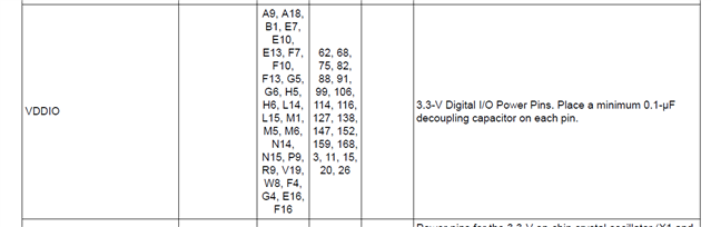
The 'TMS320F28384x Real-Time Microcontrollers with Connectivity Manger June 2023' datasheet states in Table 6-1, Pg. 49 for VDDIO that for each "3.3V Digital I/O Power Pin, Place a minimum 0.1uF decoupling capacitor on each pin". There's essentially no way to place a 0.1uF capacitor per pin given there is 32 pins and some of them are embedded with the BGA and you no access to them.
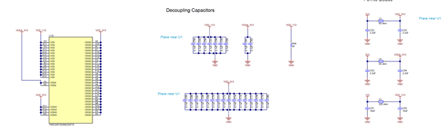
Our approach has been to place as 16 0.1uF near VDDIO pins as well as a 2.2uF capacitor bringing our total capacitance on that bank up to 3.8uF of capacitance, which is greater than the 3.2uF minimum called out in the datasheet. We designed this similar to the TMDSCNCD28388D demo board configuration. (Picture below).
I just want to get clarification that this is acceptable, although it is contrary to the datasheet.