This thread has been locked.

If you have a related question, please click the "Ask a related question" button in the top right corner. The newly created question will be automatically linked to this question.

TMS320F280033: Flashed code not running after CPU reset or power cycle

Part Number: TMS320F280033
Other Parts Discussed in Thread: C2000WARE,

Hi,

My flashed code works fine on the first build but does not load after CPU reset or power cycle.

Upon CPU reset, the code is initially stuck at 0x3fdba4 with the following warning statement:

Break at address "0x3fdba4" with no debug information available, or outside of program code.

If I hit Resume, it gets stuck at 0x3fb8b9 with the statement:

Break at address "0x3fb8b9" with no debug information available, or outside of program code.

Further information:

CCS version: 12.7

Compiler version: TI v22.6.1.LTS

Output Format: eabi (ELF)

Linker command file: F280033_flash_lnk.cmd

C2000ware version: 5.02

I have added --

Predefined symbol: _FLASH

Program entry point for the output module: code_start

I am using TMS320F280033 on my custom hardware along with XDS100v2 debug probe. Both the boot mode pins are pulled up using 4.7k resistors.

NOTE: There was a build error with F280033_flash_lnk.cmd linker command file-

"../F280033_flash_lnk.cmd", line 45: error #10468-D: The memrange group 'MEMORY_GROUP_1' contains a gap. 'BEGIN' ends at address 0x80002 and 'FLASH_BANK0_SEC8' starts at address 0x88000. Group cannot contain gaps."

so I modified line #48 of the linker command file to -   

BEGIN               : origin = 0x00088000, length = 0x00000002

and line #51 to -

FLASH_BANK0_SEC8  : origin = 0x088002, length = 0x000FFE

after which I could successfully build the program and test the code. However, the problem of flashed code not loading after CPU reset or power cycle still exists.

Any help on this issue would be greatly appreciated.

  • The origin address issue you mention is a bug, on the F280033 device the first address of bank 0 flash is 88000h, and not 80000h so the change you made is the right one there.

    I think the other issue may be the default flash boot mode entry point, but before I have you change anything in you BOOTDEF values I would like to verify the contents of the TI OTP for this device to see if there is a more straightforward soln.

    Once you are connected to the device with Code composer, open a memory browser by going to the top toolbar View->Memory Browser

    This will open a new memory view, the very first icon on the right hand side will look like a small green IC with a white arrow that points up/right. 

    Click on this to open the "Save Memory" dialogue box. 

    Create a file name and leave the format drop down alone and click "next". 

    Change the format to 16-bit Hex C Style, enter 0x70000 as the start address and 0x400 as the length.

    Then click "finish" and upload the .dat file back to this post.

    Best,
    Matthew

  • Thanks for this, the data is what I expected, for this device, since flash address 0x80000 is not present, and this is the default flash entry point address, we will need to make use of the customer boot option to assign 0x88000 for the flash entry point.

    The below is also in the device TRM https://www.ti.com/lit/spruiw9 , but I'll try and summarize here in the thread as well.  You can wait to program the Z1 OTP locations till then end  to simplify that process.

    1)Since we are adding support for custom boot, the default boot pins/modes are not the default any more.  Depending on what you want to do, this may be more flexible from a system POV, only needing 1 pin vs the 2, etc.  Assuming you don't need a serial loader, I would recommend 1 boot pin(0 is an option), we will assign one of the modes to flash and the other to "Wait" boot mode, to make emulation connection easier if needed.

    2)Now we need to decide on the boot pins.  For simplicity, I'm just going to re-use one of the 2 existing pins, GPIO24, since you already have a jumper on it.

    We will write this value to the Z1-BOOTPIN-CONFIG 

    We will write 0x5AFFFF18, which will set BMSP0 to GPIO24 and the others to "disabled"

    So 0x5AFFFF18 will go into Z1-GPREG1

    3)Next we need to pick our boot modes and set the pins, and entry points

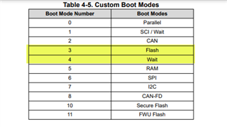
    We are going to use Boot Mode Numbers 3(flash) and 4(Wait)

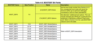
    We will be programming this, along with the flash entry point to the BOOTDEF(DEF0 and DEF1 to be exact) fields I mentioned before in the OTP, so Z1 BOOTDEFLOW/HIGH

    For BOOT_DEF0 we want to use that as Wait Boot, as this will correspond to GPIO24 = 0

    So BOOT_DEF0 = 0x04 

    BOOT_DEF1 we want to use this as flash boot, and this will correspond to GPIO24 =1

    So BOOT_DEF1 = 0x23   This will set the entry point to 0x88000 and set this to flash boot

    So BOOTDEFLOW = 0xFFFF2304 this will go in Z1-GPREG3

    BOOTDEFHIGH is unused so we will leave it 0xFFFFFFFF(Z1-GPREG4)

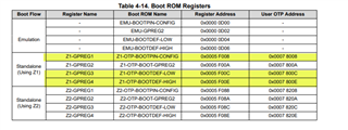
    You will need to modify the Z1-GPREG1/GPREG3 locations, these correspond to BOOTPIN-CONFIG and BOOTDEF-LOW respectively

    In CCS if you open the flash tools and scroll down you will see these locations(disregard GPREG2 from my setup below, just leave as is):

    After you do all the above, we should be able to test out the corrected flash boot mode.

    Best,
    Matthew

  • Hi Matthew,

    I am not able to understand which option does 0x13 correspond to in BOOT_DEF1 value? I see only even numbers for bits 7:4 in TRM (refer to the attachment). I feel like it should be 0x23 to direct to the address 88000h and that BOOTDEFLOW would be 0xFFFF2304. Am I missing something?

    Please confirm.

  • You are correct, I should have C/P that table as well to double check my settings! I have gone back and correct the previous post, so others don't get confused.

    Also, you can try this out in the Emulation registers you see in the Boot ROM Registers in my above reply.  This will let you test the above before programming the OTP.

    Best,
    Matthew

  • Thanks Matthew, the issue is resolved. I am able to make it boot from flash after correcting the boot mode.