This thread has been locked.

If you have a related question, please click the "Ask a related question" button in the top right corner. The newly created question will be automatically linked to this question.

LAUNCHXL-F28379D: RS485 communication (enable pin)

Part Number: LAUNCHXL-F28379D

Hello there,

I am trying to create a simple rs485 communication example with launchxl-f28379d board for that I am using SCI_B module.

I have a SP3485 device (a rs485 driver) that I would like to drive from tx, rx and enable pin of launcxl-f28379d.

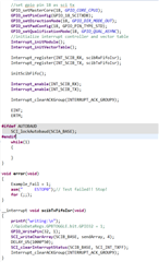
I have created two interrupts (one for Tx and one for Rx) and I have configured the TX (GPIO 19), RX (GPIO 18) and Enable (GPIO 32) but I guess problem is the enable pin (I can't see enable pin go high or low on oscilloscope neither do I see any Tx pin data). Looks like its not being properly configured. More importantly I would like to know how to enable and disable this pin for transmitting and receiving data (I know you have to set it high for transmitting and low for receiving if I am not wrong).

Basically, I would appreciate if you guys could provide a small code snippet how this enable pin works or could point me to simple complete example of rs485. Note: I don't really have to use interrupts if there is a simpler way to transmit and receive, please let me know about that too. Find my code snippets attached. 

  • Hi Sumit,

    To clarify, are you trying to transmit and receive at a different times and then use the GPIO32 pin to identify which action (transmit or receive) should be occurring? We can't offer support specifically regarding the SP3485 device, but if you can help to describe more context of what you are needing from the F28379D side that would help (the enable should be a driven output from the F28379D, correct?).

    With FIFO mode, you should immediately get a TX interrupt trigger to start communication - do you suspect your TX ISR is not being called properly? Can you please place a breakpoint in the TX ISR to verify that the breakpoint is indeed getting hit and the ISR is being called?

    Can you also try using the "Step over" button to step over each line of code while viewing the registers for SCIB and GPIOs using the CCS "Registers" window with continuous refresh on? This will help you to check that the registers are getting configured properly with each line of your code. 

    Best Regards,

    Allison

  • Hello Allison,

    For your questions:

    To clarify, are you trying to transmit and receive at a different times and then use the GPIO32 pin to identify which action (transmit or receive) should be occurring? - Yes

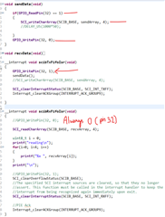
    do you suspect your TX ISR is not being called properly? - It weird, if I put a print statement in my tx interrupt it prints for a while then stops but if I put a breakpoint it didn't get hit (Note: my program running from the flash, hence can only put up to two breakpoints and ISR are hardware breakpoint). Value of my GPIO pin 32 is not changing (I checked it through register value option in CCS and via oscilloscope). I have done small modification to my program, please see below and let me know if this is the correct way to enable and disable of transmission and reception of data:

    //pin set up

    //transmit  and receive logic

  • Hi Sumit,

    Very very strange that you can print but the breakpoint is not hit.

    Were you able to you also try stepping through the code? Are the SCI registers getting set up as expected still? Are both RX and TX ISRs not getting called?

    Can you try to set up your GPIO32 similar to how you are initializing the other GPIOs?

        GPIO_setPadConfig(32, GPIO_PIN_TYPE_STD);
        GPIO_setQualificationMode(32, GPIO_QUAL_ASYNC);
        GPIO_setDirectionMode(32, GPIO_DIR_MODE_OUT);
        GPIO_setControllerCore(32, GPIO_CORE_CPU1);
    And then continue to use  GPIO_writePin(32, outVal);  to write the pin high or low.
    Best Regards,
    Allison
  • Allison,

    I made some progress and came across few things that I need to clarify:

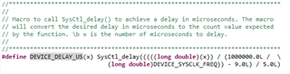
    1. What is the difference between DEVICE_DELAY_US() and DELAY_US() functions?

    2. What is the difference between GPIO_writePin(32, outVal) with small 'w' and GPIO_WritePin(32, outVal) with capital 'W' because this is the issue I found, I have been using the GPIO_WritePin(32, outVal) and it was not setting my pin 32.

    3. is GPIO pin # different than normal pin #, what I mean is there is macro called (#define GPIO_32_GPIO32   0x00460000U) and looks like I can't take it as pin 32 since it has some different hex number, so I used decimal number 32 as pin which worked for me.

    Now the issue I am having is with the transmission:

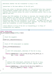
    I am trying to transmit an array of uint16_t [0x02, 0x03, 0x04, 0x05], I can see I am transmitting something but how do I make sure that I have transmitted all the bytes? I know there is a API that I am using but it doesn't guarantee that transmitter is not busy even if it is empty. Main question is how do make sure that the transmission fifo is empty and at the same time transmitter is not busy so i can pull my enable pin (rts) low to receive data. Below is my code and that API section:

    I am checking two things here: checking the status register and isBusy API, but looks like they fetch the same thing

  • Hi Sumit,

    Glad to see some progress! I've unfortunately had limited time to look deeper into this today, so please allow another day for me to form a response. 

    Thanks & Regards,

    Allison

  • Hello Allison,

    Did you get some time to look into this?

    thanks,

  • Hi Sumit,

    Sorry for the delay. To answer your questions:

    1. DEVICE_DELAY_US() is sourced from the device.h and should take into account the device SYSCLK:

    2. Where are you seeing the function with a capital "W"? A handy trick to help identify the true differences in these functions is to 'build' your program and the hold down the 'ctrl' button and click on the function name. You can similarly right-click on a function and open the declaration. This should open the source file where the function is defined and take you to the source code of the function. I've done so with the function and see the following:

    3. The "GPIO" terminology as separate from "pin". So GPIO numbers are indeed separate from pin numbers. When we talk about GPIO numbers, we are discussing signal names (e.g. GPIO0, GPIO1, etc). When we talk about pin numbers, we are referring to the physical pins on the board. For example, you could have a GPIO0 signal routed out through Pin 40 on the LaunchPad, however the GPIO0 signal may be routed out at a different physical pin number on the ControlCard (e.g. Pin 49). 

    In this case, the function GPIO_writePin() is used to write a value to the physical pin of a given GPIO. The "pin" parameter refers to the GPIO number of the pin (so if we follow my example, it would be GPIO0 --> "0" as the input parameter, not 40 or 49 etc.). 

    For the data transmission - are you seeing some error in data? Are you scoping the lines to check that you are transmitting data correctly? What is the symptom of improper transmission that you are seeing?

    In terms of detecting when you have transmitted enough data to write your GPIO, the best way to implement this with FIFO mode is to check the TX FIFO status as you are doing. The API for checking if the transmitter is busy will implement this method if it detects you are using FIFO mode:

    Is the concern on the other device side in terms of reading in the data that is transmitted by the F2837xD device? Could you add some delay before writing the pin high if there is?

    Best Regards,

    Allison

  • Allison,

    I added some delays in both (Tx and Rx), it works but communication stays for like 15 mins then stops. I will keep looking into it.

    Thanks,

  • Hi Sumit,

    Glad to see there is some progress in successful communication. Let me know if you are able to discern what is causing a break in communication or other symptoms of the issue. Looking forward to your update.

    Best Regards,

    Allison