This thread has been locked.

If you have a related question, please click the "Ask a related question" button in the top right corner. The newly created question will be automatically linked to this question.

TMS320F28388D: Problem with DMA + SPI reception buffer

Part Number: TMS320F28388D
Other Parts Discussed in Thread: SYSCONFIG, C2000WARE

Hello,

I'm coming to you because I've had a problem for a while that I can't seem to solve.
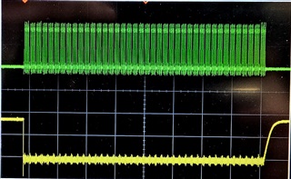
I have two microcontrollers that communicate with each other via SPI. My SPI works in full duplex, my slave receives information from the master correctly and sends data back at the same time. The signal is clean on the oscilloscope.

My problem is with reception on the TMS320F28388D configured as Master with SPI + DMA.
When I start a transmit/receive, the start of my received frame starts at the 4th byte of my receive buffer.

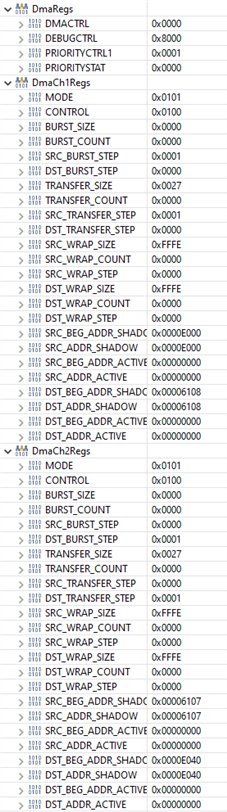
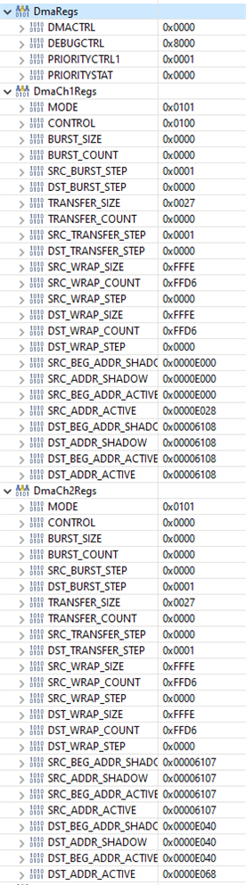
Here my DMA settings :

    /*********************************/
    /* DMA Channel 1, SPI-A transmit */
    /*********************************/
    GV_sDmaRegs.CH1.MODE.bit.CHINTE   = 0;          /* 0: Interrupt disabled                                        */
    GV_sDmaRegs.CH1.MODE.bit.DATASIZE = 0;          /* 0: 16-bit data transfer size                                 */
    GV_sDmaRegs.CH1.MODE.bit.ONESHOT  = 0;


    GV_sDmaRegs.CH1.BURST_SIZE.all    = 0;          /* 1 word/burst                                                 */
    GV_sDmaRegs.CH1.SRC_BURST_STEP    = 1;          /* Move to next word in buffer                                  */
    GV_sDmaRegs.CH1.DST_BURST_STEP    = 0;          /* Don't move destination address                               */


    GV_sDmaRegs.CH1.TRANSFER_SIZE     = C_DRVDMA_SIZE - 1U; /* C_DRVDMA_SIZE transfer size in bursts                */
    GV_sDmaRegs.CH1.SRC_TRANSFER_STEP = 1;           /* Move to next word in buffer after each word in a burst      */
    GV_sDmaRegs.CH1.DST_TRANSFER_STEP = 0;           /* Don't move destination address                              */


    GV_sDmaRegs.CH1.SRC_WRAP_SIZE = 0xFFFE;         /* Put to maximum - don't want source wrap.                     */
    GV_sDmaRegs.CH1.DST_WRAP_SIZE = 0xFFFE;         /* Put to maximum - don't want destination wrap.                */


    GV_sDmaRegs.CH1.SRC_BEG_ADDR_SHADOW = (Uint32) GV_DRVDMA_transferTxDataCh1; /* Start address = DMA buffer       */
    GV_sDmaRegs.CH1.SRC_ADDR_SHADOW     = (Uint32) GV_DRVDMA_transferTxDataCh1; /* Start address = DMA buffer       */

    GV_sDmaRegs.CH1.DST_BEG_ADDR_SHADOW = C_DRVSPI_SPIA_ADDR + C_DRVSPI_SPITXBUF_OFFSET;   /* Start address         */
    GV_sDmaRegs.CH1.DST_ADDR_SHADOW     = C_DRVSPI_SPIA_ADDR + C_DRVSPI_SPITXBUF_OFFSET;   /* Start address         */


    GV_sDmaClaSrcSelRegs.DMACHSRCSEL1.bit.CH1 = 109; /* 109: SPIA_TXDMA as DMA channel 1 Trigger source             */
    GV_sDmaRegs.CH1.MODE.bit.PERINTSEL        = 1;   /* Peripheral interrupt select                                 */


    GV_sDmaRegs.CH1.MODE.bit.PERINTE          = 1;   /* Enable peripheral interrupt event                           */
    GV_sDmaRegs.CH1.CONTROL.bit.PERINTCLR     = 1;   /* Clear peripheral interrupt event flag.                      */


    /********************************/
    /* DMA Channel 2, SPI-A receive */
    /********************************/
    GV_sDmaRegs.CH2.MODE.bit.CHINTE   = 0;          /* 0: Interrupt disabled                                        */
    GV_sDmaRegs.CH2.MODE.bit.DATASIZE = 0;          /* 0: 16-bit data transfer size                                 */
    GV_sDmaRegs.CH2.MODE.bit.ONESHOT  = 0;
    GV_sDmaRegs.CH2.MODE.bit.CONTINUOUS  = 0;


    GV_sDmaRegs.CH2.BURST_SIZE.all    = 0;          /* 1 word/burst                                                 */
    GV_sDmaRegs.CH2.SRC_BURST_STEP    = 0;          /* Don't move in FIFO                                           */
    GV_sDmaRegs.CH2.DST_BURST_STEP    = 1;          /* Move to next word in destination address                     */


    GV_sDmaRegs.CH2.TRANSFER_SIZE     = C_DRVDMA_SIZE - 1U; /* C_DRVDMA_SIZE transfer size in bursts                */
    GV_sDmaRegs.CH2.SRC_TRANSFER_STEP = 0;           /* Don't move source address                                   */
    GV_sDmaRegs.CH2.DST_TRANSFER_STEP = 1;           /* Move to next word in buffer after each word in a burst      */


    GV_sDmaRegs.CH2.SRC_WRAP_SIZE = 0xFFFE;         /* Put to maximum - don't want source wrap.                     */
    GV_sDmaRegs.CH2.DST_WRAP_SIZE = 0xFFFE;         /* Put to maximum - don't want destination wrap.                */


    GV_sDmaRegs.CH2.SRC_BEG_ADDR_SHADOW = C_DRVSPI_SPIA_ADDR + C_DRVSPI_SPIRXBUF_OFFSET;   /* Start address         */
    GV_sDmaRegs.CH2.SRC_ADDR_SHADOW     = C_DRVSPI_SPIA_ADDR + C_DRVSPI_SPIRXBUF_OFFSET;   /* Start address         */

    GV_sDmaRegs.CH2.DST_BEG_ADDR_SHADOW = (Uint32) GV_DRVDMA_transferRxDataCh2; /* Start address = DMA buffer       */
    GV_sDmaRegs.CH2.DST_ADDR_SHADOW     = (Uint32) GV_DRVDMA_transferRxDataCh2; /* Start address = DMA buffer       */


    GV_sDmaClaSrcSelRegs.DMACHSRCSEL1.bit.CH2 = 110; /* 109: SPIA_RXDMA as DMA channel 1 Trigger source             */
    GV_sDmaRegs.CH2.MODE.bit.PERINTSEL        = 1;   /* Peripheral interrupt select                                 */


    GV_sDmaRegs.CH2.MODE.bit.PERINTE          = 1;   /* Enable peripheral interrupt event                           */
    GV_sDmaRegs.CH2.CONTROL.bit.PERINTCLR     = 1;   /* Clear peripheral interrupt event flag.                      */

With :

C_DRVSPI_SPIA_ADDR = 0x006100U

C_DRVSPI_SPIRXBUF_OFFSET = 0x07U

C_DRVDMA_SIZE  = 40U

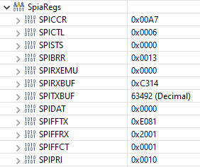
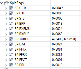
And here my SPI settings

    /* SPI-A Clear SPI Software Reset bit (SPISWRESET=  to 0 to force the SPI to the reset state */
    /* SPI-A Relinquish SPI from Reset, Reset on, rising edge in input, 8-bit char bits */
    GV_sSpiARegs.SPICCR.all = 0x0007U;

    /* SPI-A Master mode, normal SPI clocking scheme, enable talk and disable SPI interrupt (flag) */
    GV_sSpiARegs.SPICTL.all = 0x0006U;

    /* SPI-A Baud Rate is set */
    GV_sSpiARegs.SPIBRR.all = 19U;

    /* SPI-A FREE bit */
    /* Halting on a breakpoint will not halt the SPI */
    GV_sSpiARegs.SPIPRI.bit.FREE = 1;

    /* SPI-A RX FIFO, RXFIFORESET: Reset the FIFO pointer to zero, and hold in reset. */
    GV_sSpiARegs.SPIFFRX.all = 0U;

    /* SPI-A TX FIFO, SPIRST: Reset the SPI transmit and receive channels.                 */
    /*                        The SPI FIFO register configuration bits will be left as is. */
    /*                TXFIFO: Reset the FIFO pointer to zero, and hold in reset            */
    GV_sSpiARegs.SPIFFTX.all = 0U;

    /* SPI-A RX FIFO interrupt is disabled, FIFO interrupt level bits to default value */
    /* SPI-A is ready to receive (RX FIFO) */
    GV_sSpiARegs.SPIFFRX.all = 0xE041U;

    /* SPI-A Enable TX and RX FIFO and is ready to transmit (TX FIFO) */
    GV_sSpiARegs.SPIFFTX.all = 0xE041U;

    GV_sSpiARegs.SPIFFCT.all = 1;

    /* SPI-A is ready to transmit and receive the next character, set this bit before resuming operation */
    GV_sSpiARegs.SPICCR.bit.SPISWRESET = 1;

When I start a transmission/reception :

  • I start first the RX DMA :

GV_sDmaRegs.CH2.CONTROL.bit.PERINTCLR = 1;
GV_sDmaRegs.CH2.CONTROL.bit.RUN = 1;

  • Then TX DMA:

GV_sDmaRegs.CH1.CONTROL.bit.RUN = 1;

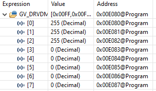
Systematically, at start-up, the first 3 bytes of my DMA buffer are the current state of SPIRXBUF repeated 3 times, and then 4 bytes lost from my frame (= 0) and then part of my expected frame.

Example :


Expected: 

  • [0] --> 0x5A
  • [1] --> 0 (Counter)
  • [2] --> 2
  • [3] --> 3
  • [4] --> 4
  • [5] --> 5
  • [6] --> 6
  • [7] --> 7
  • ...
  • [37] --> 37
  • [38] --> 0 (Same counter)
  • [39] --> 0xA5

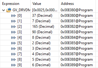
All next transmission/reception, I have :

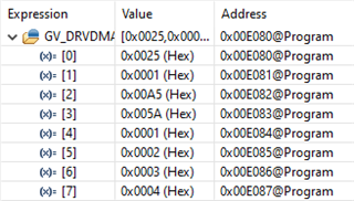
My counter is the same at [4] as at [1], so I interpret that I have received my entire frame, but my DMA has started writing at the 4th byte and looping (even though I don't have WRAP set).

In debug, a breakpoint after activating DMA RX and before DMA TX shows no DMA RX trigger, only when I activate TX.

If you have any clues, I can't understand this problem. Thanks !

  • Damn, I can't update my post, anyway, I'll do it here:


    I've fixed a problem with my slave's transmission.

    This corrected a problem with my counter which appeared identical on bytes [4] and [1] because now I have something consistent.

    My first frame received (all 0s) looks like this on the Master:

    After several receptions :

    90 should be the [0] and 165 the [39]

    The problem is still the same, my receive buffer always starts on the 4th. And I receive the second part of my frame at the next DMA activation.

    I hope that's clear to you Grimacing

  • Armageddon,

    To make sure I understand, the controller, SPI-A, transmits using channel 1 and receives using channel 2. The target, let's say SPI-B, transmits using channel 2 and receives using channel 1. SPI-B is receiving and sending the data correctly (scope shots show this), and SPI-A is not receiving and sending the data correctly because the data is starting on a different frame than expected. The system is using FIFOs on both SPI-A/B side along with the DMA.

    Can you confirm that the scope of the controller looks accurate? Give me one day to review your code and get back to you in the mean time as well.

    I've fixed a problem with my slave's transmission.

    Can you clarify what you fixed in the code provided above?

    Aishwarya

  • You've got it right. The SPI-A uses a FIFO, it transmits correctly (I think) because I have no problem decoding a frame on the slave side (SPI-B).

    On the oscilloscope, I can see my 40 bytes.

    The start and end bytes are well positioned. (MOSI and MISO).

    In my first frame, for example, MISO is low throughout transmission and my DMA only writes 0 from the 4th byte of my receive buffer (SPI-A).

    The problem is identical to the next reception, except that there is data and the end of my reception N is displayed at the beginning of my buffer at reception N+1.

    My main issue is why I can't start my reception (SPI-A) at the beginning of my buffer, always 4 bytes later.


    I haven't corrected anything in the code above, one of my problems was on the slave side (SPI-B). My transmission buffer was modified during transmission, resulting in inconsistent frames on the master side (SPI-A), such as 0's and then data at the beginning of the frame.

    My first received frame is ONLY 0's. Then I get data in the next frames.

    The forum seems to have a problem editing a post, I'm sorry my first post was confusing.

    Thank you for your help

  • Armageddon,

    Notes related to the SPI:

    Since the SPI is operating with the DMA, there is a specific configuration requirement of that the RXFFST is greater than or equal to RXFFIL. Right now, it looks like it's the opposite which inhibits activating the SPIRXDMA. Attaching the other relevant information for SPI DMA operation just to take a look.

    The SPICCR.SPICHAR = 0x7U (8-bit word transmission), so make sure the sent data is left-justified since SPI is optimized for 16-bit transfers. It is suggested to enable high speed mode to reach full duplex speeds, but it is not a requirement, and also make sure that the SPIs have the same clock frequency.

    Can you also confirm the following:

    1. What is seen in the SPI RX/TX FIFO and the SPIDAT registers?
    2. Why is GV_sSpiARegs.SPIFFCT.all = 1;?

    Notes related to the DMA:

    Overall, I think there are some settings done with one channel not done with the other, so need to make sure you're setting all relevant bits. Refer to the SPI DMA example for more info on DMA settings in this context.

    1. Does CH1 have high priority?
    2. When does the DMA generate an interrupt (MODE.CHINTMODE)? Is continuous mode disabled (MODE.CONTINUOUS)?
    3. Are the DMA interrupts are working as expected? You shouldn't need to configure separate SPI interrupts since the SPI transfer is the trigger for the DMA, but you do need to enable DMA channel interrupts.

    In addition, if you haven't taken a look at SysConfig / Driverlib, I would highly suggest doing so as it simplifies the configuration process since it generates that code. 

    Aishwarya

  • Hello Aishwarya Rajesh,

    To answer your questions, I made the following changes before relaunching my tests:

    • I've switched the CH1 to high prority with CH1PRIORITY = 1
    • I have updated the interrupt on my channel 2 (RX) to use SPIA_TXDMA (109)
    • I've activated the SPI High-Speed Mode.

    Before showing you my results:

    • GV_sSpiARegs.SPIFFCT.all = 1 because it made it easier for me to see my bytes with the scope
      I tried setting it to 0 and 5, but didn't notice any change.

    • MODE.CHINTMODE is set to 0 for both channels.
      I also tried setting it to 1 for both channels and I didn't see any change either.

    • I didn't forget to send my data in left-justified. I have no problem seeing my frame on the slave side.

    Here is the state of my registers after initialisation:


    When I start the DMA RX (CH2), the registers don't move except for DmaCh2Regs.CONTROL = 0x2000 (because RUNSTS = 1).

    Now here's the state of my registers, after enabling DMA TX (CH1):


    The result is identical, on my first reception, I have 3 identical bytes of the SPIRXBUF value and then my 0.

    For what it's worth, here's a picture of the signal from my first frame. Green signal is SCK and yellow is MISO.


    Thank you again for your help ! Pray

  • Hi Armageddon,

    Thanks for confirming. CH1PRIORITY doesn't need to be enabled, but it should be fine either way. You may just need to check the OVERRUN_FLAG bit in the SPISTS register since the SPITXDMA is prioritized causing an overrun of the RX FIFO.

    In terms of SPI, make sure that in addition to the receive data, the transmit data is being stored as 16-bit values on the target.

    If you haven't already, I would also try running the code without breakpoints in the interrupts and pause at a random moment to see if that fixes the issue. In case the scope shots are from running with breakpoints, this can help if the issue is CCS debugger and not software setup related.

    Aishwarya

  • Hello Aishwarya Rajesh,

    I can't see OVERRUN_FLAG set to 1 when, according to the documentation, this bit is cleared in one of three way

    - Writing a 1 to this bit

    - Writing a 0 to SPI SW RESET (SPICCR.7)

    - Resetting the system

    So I don't have any overflow.

    In terms of SPI, make sure that in addition to the receive data, the transmit data is being stored as 16-bit values on the target.

    As I said before, I can decode my transmission on the slave.

    • I didn't forget to send my data in left-justified. I have no problem seeing my frame on the slave side.

    I tried your suggestion, I started the code without breakpoint and the behaviour is the same. My frame starts at the 4th byte.

    I've sent you a screenshot of all my DMA + SPI registers and the behaviour is still inconsistent.
    Can you reproduce the problem on your side? Or am I the only one?

  • Armageddon,

    Using the C2000Ware SPI DMA example #5 and your settings, I did not see an issue. If you can send me a friendship request, we can take a look at your SPI and DMA runtime code. In the mean time, let me look into the issue further on my side as well.

    Aishwarya 

  • Thank you for trying to help me.

    Unfortunatly, I won't be able to access to the device before 13 May.
    I will try next time to work with C2000 lib to check if any diferences.
    Thank you

  • Armageddon,

    Few more things you can try, if you haven't already.. make sure the SPI polarity/clock mode are the same for the SPIs, check the SPI/DMA GPIO settings (SPI should be async), and make sure you have a separate TX and RX ISR in which you make sure to clear the interrupt group before exiting the ISR.

    These suggestions are based on configurations alone. Do you have access to your program code? It does not need to be running, if that is what you mean.

    Aishwarya