This thread has been locked.

If you have a related question, please click the "Ask a related question" button in the top right corner. The newly created question will be automatically linked to this question.

LAUNCHXL-F28379D: Error 2131 using Code Composer Studio V10.2.0

Part Number: LAUNCHXL-F28379D
Other Parts Discussed in Thread: BOOSTXL-3PHGANINV

Hello, 

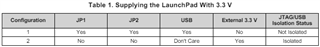
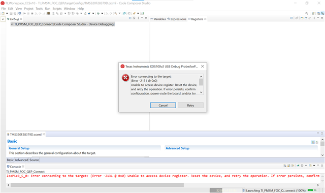
I'm currently getting an error 2131 when I try connecting to the target device. I'm using CCS V10.2.0. I currently have two different boards. The first board was working and it recently started having this issue. The second board started having the same issue straight out of the box. I also have a BOOSTXL-3PhGaNInv board connected to the launchpad. However, I get the error with or without the daughter board connected to it. My guess is that some of the jumper wires or switches are not being set to the correct position.  I have included a picture of the current jumper and switch settings as well as the error I'm getting when trying to connect to it. 

I also noticed that the solution to a similar issue was to connect the JP1 jumper. Can I still do this even if I have to supply power from the BOOSTXL-3PhGaNInv board

Thank you! 

  • Hello Nelson,

    Below is how the JP1 jumper configures the LaunchPAD:

    Is the BOOSTXL-3PhGaNInv powering the LaunchPAD directly? If not, I don't think there's any change in how the jumper should be configured. Please refer to the LAUNCHXL-F28379D Overview guide for more information.

  • Hello Omer, 

    Thank you for your quick response. The original set up I had when the board was working had the JP6, JP4 jumpers connected, and the rest of the jumpers disconnected.  We also had the BOOSTXL-3PhGaNInv board connected to it and powered up with an external 24V PSU. Do you know if this set up is correct? We are still seeing the error 2131 even with those settings. Please see our hardware set up below. 

    Thank you! 

  • Hi Nelson,

    Your jumper connections look correct for the isolated case from what I can see. Can you probe a 3V3 test point on the launchpad and check that it is getting the correct power output from the boosterpack?

    Can you try connecting to the device in the nonisolated case with the boosterpack removed and the launchpad in standalone? You should ensure that JP1 JP2 and JP3 are connected. And that the jumper on JP6 is disconnected to avoid contention on the 5V rail. It is optional to connect JP4/JP5, those merely provided 3V3 and 5V to the bottom site headers.

    Regards,

    Peter

  • Hello Peter,

    Thank you so much for providing additional information. After probing the board here's what we found:

    Board #1 - Launchpad by itself (old board that worked before)

    JP1, JP2, JP3 are connected, JP6 is disconnected. 

    We measured at the same point as the previous test. We got 5V on the 5V pins and 0.3V on the 3V3 pins. 

    NO LED lights were On, on the board. 

    -----------------------------------------------------------------------------------------

    Boards #1 - LaunchPad + Booster Pack (old boards that worked before)

    JP6 connected & JP1, JP2, JP3 disconnected. 

    No power to the 3.3V, 5V pins. I measured the pins that are next to the quadrature pins. (Bottom of the board with the TI logo facing up- opposite to the micro-USB connector). We measured roughly 0.3 V on the 5V and 0.2V on the 3V3. 

    The LED D4 was on. LED's D7, D8 were also on/off every 3secs roughly. The LED D5 on the Booster Pack was also on. 

    -------------------------------------------------------------------------------------------

    Boards #2 - LaunchPad  (Brand new board)

    JP1, JP2, JP3 are connected, JP6 is disconnected. 

    We measured at the same point as the previous test. We got 5V on the 5V pins and 3V on the 3V3 pins. 

    LED's D4, D9 and D1 are On. 

    D10 was flashing blue for about half a second.

    -------------------------------------------------------------------------------------------

    Boards #2 - LaunchPad + Booster Pack (Brand new boards)

    JP1, JP2, JP3 are disconnected, JP6 is connected. 

    We measured at the same point as the previous test. We got 5V on the 5V pins and 3v3 on the 3V3 pins. 

    On the launchpad, D1, D9 and D4 were originally on. 

    On the boosterpack D5 and D6 are On. 

    After seeing better results with these boards, we decided to deploy the software and it seemed like it worked. After doing that LED D9 went off and D10 started flashing blue. 

    We then undeployed and redeployed and all of the following LED's were On.

    Laucnhpad - D1, D4, D9, D10

    BoosterPack - D5, D6

    -------------------------------------------------------------------------------------------

    Would you be able to confirm that this is normal behavior? Thank you so much Peter and Omer for contributing to this solution! 

  • Hi Nelson, 

    It seems your old board may have been damaged, is that the board that is pictured in the image? Can you measure all 3.3V pins on the boosterpack headers as well as the 3.3V test point on the board? The jumpers that are populated should be enough to provide the 3.3V power and the power good LEDs should be lit in this instance

    Regards,

    Peter