This thread has been locked.

If you have a related question, please click the "Ask a related question" button in the top right corner. The newly created question will be automatically linked to this question.

LAUNCHXL-F280049C: 90 degress delay in start between PWM7 and PWM8

Part Number: LAUNCHXL-F280049C
Other Parts Discussed in Thread: C2000WARE

Hi,

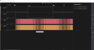
I am generating PWM signal for my power electronics project and I would like to verify the behaviour of my PWMs.

I am using PWM7 at 50 Hz and PWM8 at 20Khz and PWM7 is the master.  The initialisation code of both are called at the same time, PWM7 first then pwm8.  However, there is always a 90 degree difference in the start of both pwm, i.e, the PWM8 starts after a delay of 90 degrees.  

I want to ask if this is abnomal and how can I configure the two PWM to start at the same time (without this 90 degree delay).

Thanks

  • Hi Abayomi,

    How are you currently configurating and then starting up the EPWMs? Generally, you should disable sync and freeze the clock for the PWM, then configure the PWM and set the PWM counter to zero, and finally enable sync and the EPWM clock to start the PWMs at the same time.

    Did you already reference some of our C2000Ware examples ({C2000Ware}\driverlib\f28004x\examples\epwm)? These show this flow as well.

    Best Regards,

    Allison

  • Hello Allison,

    Thanks for your prompt reply.

    The above sequence was what I used in the configuration of my EPWMs.  A snapshoot of the waveform is below

    The waveform marked P0 is the PWM7 and it should be 20ms and not 15ms and this is the first pwm (duty cycle) at the starting of the pwm.  This lead to the permanent 90 degress delay, which is propagated through the entire waveform

    The waveform marked P1 is for the pwm8 and this pwm starts normally and ends normaly which is for a period of 20ms.

    I have reviewed the entire code but I did not fine the cause of the problem.  I have also looked at the pwm examples but could not solve the problem.

    I anticipate your feedback.

    Thanks.

  • Hi Abayomi, 

    I'm a bit confused by the image you shared - are your PWM waveforms all shown on channels D0-D3? How are P0 and P1 generated? P0 and P1 refer to the period of the PWMs? Are you still seeing the correct frequency outputs? Just want to be sure I'm understanding and interpreting correctly.

    In your initializations in main() are you starting all of the EPWM counters at the same time? The TBCLKSYNC bit when set will start the time base counter (TBCTR) for all of the epwm modules within the corresponding CPU selected. From the device TRM:

    Best Regards,

    Allison

  • Hello Allison,

    Thank you for your reply.  I would go through my implmentation and ensures the above points are implemented and then give you an update.

    To the questions you raised.

    1.  The red pwm train is for pwm7 and at 50 Hz.

    2. The orange pwm train is for pwm8 and at 20khz.

    3. The both pwms are meant to start at the same time and when the pwm7 completes a cycle, the pwm8 should have made 400 cycles or a period of 20ms but in the waveform we see that the first duty cycle of the pwm7 does not correspond to this. Hence this permanent delay of 90 degress.

    3.  The markings are to look at the timing of the pwm trains.  The two PWM are started together and a should be alligned but this is not the case

    4. The marker P0 shows that the first pwm cycle of the pwm7 is not a complete cycle of 50Hz (20ms) but is is trucated to 15ms.  All other duty cycles are correct but this 5ms that is cut off the first duty cycle removes the allignment from the two pwms

    5. The marker P1 shows pwm8.  It starts as expected and after 400 cycles gives a totatl period of 20ms or frequency of 50Hz.

    I hope this helps explain my observation and problem with pwm.

    Thanks.

  • Hi Abayomi,

    Thanks for the responses. 

    Yes please check that your application is starting up the EPWMs as I mentioned and let me know.

    Could you also please share your EPWM configurations? What are your action qualifiers?

    Best Regards,

    Allison

  • Hi Allison,

    Thanks for your reply again.

    I have thoroughly verified my code and implemented all our chats and tested the code but the situation is still the same.

    I am attaching the pwm code for you to reveiw for me.

    **
     * @brief  initialization of the PWM module for the DC2AC converter
     * @param  void
     * @retval None
     * @details  pwm is generated at a period of 20kHz and 50 Hz for the modified unipolar modulation technique Q5, Q6, Q7 and Q8 are driven
     *         epmw7 and 8 are used
     */
    void epwm::InitDC2AC(void)
    {
    
        /******************************************************************
         *  Initialization of the  ePWM7  and epwm8 for driving of dc2ac mosfets
         *  ePWM7 = 50Hz, epwm8 = 20kHz
         *
         *         epwm8a ->   Q1           epwm7b  ->  Q2
         *
         *
         *         epwm8b  ->  Q4           epwm7a  ->  Q3
         *
         ******************************************************************/
    
        /******************************************************************
         *  Initialization of the  ePWM7 for driving of transistors mosfets
         *  ePWM7 = 50Hz
         *
         ******************************************************************/
    
        SysCtl_enablePeripheral(SYSCTL_PERIPH_CLK_EPWM7);
        asm(" RPT #5 || NOP");
    
        Interrupt_register(INT_EPWM7, &epwm::EPWM7ISRDC2AC);
    
        /**< configuration of the ePWM8 */
        /**< reset peripheral before initialization */
        SysCtl_enablePeripheral(SYSCTL_PERIPH_CLK_EPWM8);
        asm(" RPT #5 || NOP");
    
        /**< Interrupts that are used are re-mapped to ISR functions found within this file. */
        Interrupt_register(INT_EPWM8, &epwm::EPWM8ISRDC2AC);
    
        /**< disable peripheral for initialization */
        SysCtl_disablePeripheral(SYSCTL_PERIPH_CLK_TBCLKSYNC);
    
    
        //SysCtl_setSyncOutputConfig(SYSCTL_SYNC_OUT_SRC_EPWM7SYNCOUT);
        //SysCtl_setSyncInputConfig(SYSCTL_SYNC_IN_EPWM7, SYSCTL_SYNC_IN_SRC_EXTSYNCIN1);
    
        /**< configuration of the ePWM7 */
        /**< reset peripheral before initialization */
        SysCtl_resetPeripheral(SYSCTL_PERIPH_RES_EPWM7);
    
        /**< Set up TBCLK */
        EPWM_setTimeBasePeriod(EPWM7_BASE, 25000);
        EPWM_setClockPrescaler(EPWM7_BASE, EPWM_CLOCK_DIVIDER_4, EPWM_HSCLOCK_DIVIDER_10);
        EPWM_setTimeBaseCounter(EPWM7_BASE, 0U);                        // Clear timer counter
    
        /**< Set up counter mode */
        EPWM_setTimeBaseCounterMode(EPWM7_BASE, EPWM_COUNTER_MODE_UP_DOWN);  // Enable the timer in count up mode
    
        /**< Set up for synchronization between ePWM */
        EPWM_disablePhaseShiftLoad(EPWM7_BASE);
        EPWM_setPhaseShift(EPWM7_BASE, 0);                             // Set timer phase
        EPWM_setSyncOutPulseMode (EPWM7_BASE, EPWM_SYNC_OUT_PULSE_ON_COUNTER_ZERO );   //sync pulse is sent when counter is 0
        //EPWM_setCountModeAfterSync (EPWM7_BASE, EPWM_COUNT_MODE_UP_AFTER_SYNC); //count up for phase shift count after sync
    
        /**< Set up compare values */       //TODO not needed
        EPWM_setCounterCompareValue(EPWM7_BASE, EPWM_COUNTER_COMPARE_A, PWM_CMPR_LF_DC2AC(INVERT_DC2AC_LF_STARTUP_DC));    // Set compare value which determines the duty cycle of the PWM_CMPR_HF_DC2AC
        EPWM_setCounterCompareValue(EPWM7_BASE, EPWM_COUNTER_COMPARE_B, PWM_CMPR_LF_DC2AC(INVERT_DC2AC_LF_STARTUP_DC));    // Set compare value which determines the duty cycle of the T2
    
        /**< Set up shadowing */
        EPWM_setCounterCompareShadowLoadMode(EPWM7_BASE, EPWM_COUNTER_COMPARE_A, EPWM_COMP_LOAD_ON_CNTR_PERIOD);   // Load on zero or PRD match
        EPWM_setCounterCompareShadowLoadMode(EPWM7_BASE, EPWM_COUNTER_COMPARE_B, EPWM_COMP_LOAD_ON_CNTR_PERIOD);   // Load on zero or PRD match
    
    
        /**< Set up action qualifier */
        EPWM_setActionQualifierAction(EPWM7_BASE, EPWM_AQ_OUTPUT_A, EPWM_AQ_OUTPUT_LOW, EPWM_AQ_OUTPUT_ON_TIMEBASE_ZERO);   // Set pin low  on when time base counter = 0
        EPWM_setActionQualifierAction(EPWM7_BASE, EPWM_AQ_OUTPUT_A, EPWM_AQ_OUTPUT_HIGH, EPWM_AQ_OUTPUT_ON_TIMEBASE_UP_CMPA);  // Set pin high when cmp a up = time base counter
        EPWM_setActionQualifierAction(EPWM7_BASE, EPWM_AQ_OUTPUT_A, EPWM_AQ_OUTPUT_LOW, EPWM_AQ_OUTPUT_ON_TIMEBASE_DOWN_CMPA);  // Set pin low when cmp a up = time base counter
    
        EPWM_setActionQualifierAction(EPWM7_BASE, EPWM_AQ_OUTPUT_B, EPWM_AQ_OUTPUT_HIGH, EPWM_AQ_OUTPUT_ON_TIMEBASE_ZERO);   // Set pin  on when time base counter = 0
        EPWM_setActionQualifierAction(EPWM7_BASE, EPWM_AQ_OUTPUT_B, EPWM_AQ_OUTPUT_LOW, EPWM_AQ_OUTPUT_ON_TIMEBASE_UP_CMPB);  // Set pin low when cmp a up = time base counter
        EPWM_setActionQualifierAction(EPWM7_BASE, EPWM_AQ_OUTPUT_B, EPWM_AQ_OUTPUT_HIGH, EPWM_AQ_OUTPUT_ON_TIMEBASE_DOWN_CMPB);  // Set pin low when cmp a up = time base counter
    
        /**< Set up for synchronization between ePWM */
        /**< for start up operation after which it is changed to running mode setting */
        EPWM_setDeadBandDelayPolarity(EPWM7_BASE, EPWM_DB_FED, EPWM_DB_POLARITY_ACTIVE_LOW);
        EPWM_setDeadBandDelayMode(EPWM7_BASE, EPWM_DB_RED, true);
        EPWM_setRisingEdgeDelayCount(EPWM7_BASE, EPWM7_DT_STARTUP);
        EPWM_setDeadBandDelayMode(EPWM7_BASE, EPWM_DB_FED, true);
        EPWM_setFallingEdgeDelayCount(EPWM7_BASE, EPWM7_DT_STARTUP);


        /****************************************************************************************************
         * configure over epwm trip zone for one time OC protection - TRIP7 and battery current protection - TRIP5
         * trip immediately shuts down th epwm unit
         ******************************************************************************************************/
    
        //based on comment from next code
        EPWM_disableTripZoneAdvAction(EPWM7_BASE) ;
    
        EPWM_setTripZoneAction(EPWM7_BASE, EPWM_TZ_ACTION_EVENT_DCAEVT1, EPWM_TZ_ACTION_LOW); //TODO verify
    
        /**< configure trip zone action for DCAEVT1 and DCBEVT1, trigger when it is high */
        EPWM_setTripZoneDigitalCompareEventCondition (EPWM7_BASE, EPWM_TZ_DC_OUTPUT_A1, EPWM_TZ_EVENT_DCXH_HIGH);
    
        /**< Configure DCAH and DCBH to use trip7 and trip5 */
        //combine trip7 and trip5
        EPWM_selectDigitalCompareTripInput(EPWM7_BASE, EPWM_DC_TRIP_COMBINATION, EPWM_DC_TYPE_DCAH);
    
        //trip7
        EPWM_enableDigitalCompareTripCombinationInput(EPWM7_BASE, EPWM_DC_COMBINATIONAL_TRIPIN7, EPWM_DC_TYPE_DCAH);
    
        //trip5
        EPWM_enableDigitalCompareTripCombinationInput(EPWM7_BASE, EPWM_DC_COMBINATIONAL_TRIPIN5, EPWM_DC_TYPE_DCAH);
    
        /**< enable trip zone signal for DCAEVT1 and DCBEVT1 and for one short tripping */
        EPWM_enableTripZoneSignals(EPWM7_BASE, EPWM_TZ_SIGNAL_DCAEVT1);
    
        /**< configure for unfiltered and asynchronous operation */  //TODO verify unfiltered
        EPWM_setDigitalCompareEventSource(EPWM7_BASE, EPWM_DC_MODULE_A, EPWM_DC_EVENT_1,  EPWM_DC_EVENT_SOURCE_ORIG_SIGNAL);
    
        /**< Set up interrupts */
        /**< Interrupts that are used are re-mapped to ISR functions found within this file. */
    
        EPWM_enableInterrupt(EPWM7_BASE);
        EPWM_setInterruptSource(EPWM7_BASE, EPWM_INT_TBCTR_ZERO);
        EPWM_setInterruptEventCount(EPWM7_BASE, 1U);
    
        /**< clear interrupt flag */
        EPWM_clearEventTriggerInterruptFlag(EPWM7_BASE);
    
        /******************************************************************
         *  Initialization of the  ePWM8 for driving of transistors mosfets
         *  ePWM8 = 20KHz
         *
         ******************************************************************/
    
        /**< configuration of the ePWM8 */
        /**< reset peripheral before initialization */
    //    SysCtl_enablePeripheral(SYSCTL_PERIPH_CLK_EPWM8);
    //    asm(" RPT #5 || NOP");
    //
    //    /**< Interrupts that are used are re-mapped to ISR functions found within this file. */
    //    Interrupt_register(INT_EPWM8, &epwm::EPWM8ISRDC2AC);
    
        /**< configuration of the ePWMA */
        /**< reset peripheral before initialization */
        SysCtl_resetPeripheral(SYSCTL_PERIPH_RES_EPWM8);
    
        /**< Set up TBCLK */
        EPWM_setTimeBasePeriod(EPWM8_BASE, 67);          // Set timer period  I_DC2AC_LF_EPWM_PERIOD
        EPWM_setClockPrescaler(EPWM8_BASE, EPWM_CLOCK_DIVIDER_4, EPWM_HSCLOCK_DIVIDER_10);   // TBCLK = EPWMCLK  EPWM_CLOCK_DIVIDER_128
        EPWM_setTimeBaseCounter(EPWM8_BASE, 0U);                        // Clear timer counter
    
        /**< Set up counter mode */
        EPWM_setTimeBaseCounterMode(EPWM8_BASE, EPWM_COUNTER_MODE_UP_DOWN);  // Enable the timer in count up mode
        //EPWM_disablePhaseShiftLoad(EPWM8_BASE);                         // Disable phase load
    
        /**< Set up for synchronization between ePWM */
    //    EPWM_setSyncOutPulseMode (EPWM8_BASE, EPWM_SYNC_OUT_PULSE_ON_EPWMxSYNCIN );   //sync pulse is received from pwm 7
    //    EPWM_enablePhaseShiftLoad(EPWM8_BASE);      //enable the phaseshift load to load the phase shift value
    //    //EPWM_setPhaseShift(EPWM8_BASE, (PWM_CMPR_LF_DC2AC(INVERT_DC2AC_LF_STARTUP_DC)));   //enable a 180 degree phase shift between both pwm  //TODO not sure
    //    //EPWM_setCountModeAfterSync (EPWM8_BASE, EPWM_COUNT_MODE_UP_AFTER_SYNC); //count up for phase shift count after sync
    
        /**< Set up compare values */
        EPWM_setCounterCompareValue(EPWM8_BASE, EPWM_COUNTER_COMPARE_A, PWM_CMPR_HF_DC2AC(INVERT_DC2AC_HF_STARTUP_DC));
        EPWM_setCounterCompareValue(EPWM8_BASE, EPWM_COUNTER_COMPARE_B, PWM_CMPR_HF_DC2AC(INVERT_DC2AC_HF_STARTUP_DC));
    
        /**< Set up shadowing */
        EPWM_setCounterCompareShadowLoadMode(EPWM8_BASE, EPWM_COUNTER_COMPARE_A, EPWM_COMP_LOAD_ON_CNTR_ZERO);   // Load on zero or PRD match
        EPWM_setCounterCompareShadowLoadMode(EPWM8_BASE, EPWM_COUNTER_COMPARE_B, EPWM_COMP_LOAD_ON_CNTR_ZERO);   // Load on zero or PRD match
    
        /**< Set up action */
        EPWM_setActionQualifierAction(EPWM8_BASE, EPWM_AQ_OUTPUT_A, EPWM_AQ_OUTPUT_LOW, EPWM_AQ_OUTPUT_ON_TIMEBASE_ZERO);   // Set pin  on when time base counter = 0
        EPWM_setActionQualifierAction(EPWM8_BASE, EPWM_AQ_OUTPUT_A, EPWM_AQ_OUTPUT_HIGH, EPWM_AQ_OUTPUT_ON_TIMEBASE_UP_CMPA);  // Set pin low when cmp a up = time base counter
        EPWM_setActionQualifierAction(EPWM8_BASE, EPWM_AQ_OUTPUT_A, EPWM_AQ_OUTPUT_LOW, EPWM_AQ_OUTPUT_ON_TIMEBASE_DOWN_CMPA);  // Set pin low when cmp a up = time base counter
    
        EPWM_setActionQualifierAction(EPWM8_BASE, EPWM_AQ_OUTPUT_B, EPWM_AQ_OUTPUT_HIGH, EPWM_AQ_OUTPUT_ON_TIMEBASE_ZERO);   // Set pin  on when time base counter = 0
        EPWM_setActionQualifierAction(EPWM8_BASE, EPWM_AQ_OUTPUT_B, EPWM_AQ_OUTPUT_LOW, EPWM_AQ_OUTPUT_ON_TIMEBASE_UP_CMPB);  // Set pin low when cmp a up = time base counter
        EPWM_setActionQualifierAction(EPWM8_BASE, EPWM_AQ_OUTPUT_B, EPWM_AQ_OUTPUT_HIGH, EPWM_AQ_OUTPUT_ON_TIMEBASE_DOWN_CMPB);  // Set pin low when cmp a up = time base counter
    
        /**< dead band configuration */
        /**< configure RED for delay of xxxms with the b comparator*/
    //    EPWM_setDeadBandDelayPolarity(EPWM8_BASE, EPWM_DB_FED, EPWM_DB_POLARITY_ACTIVE_LOW);
    //    EPWM_setDeadBandDelayMode(EPWM8_BASE, EPWM_DB_RED, true);
    //    EPWM_setRisingEdgeDelayCount(EPWM8_BASE, EPWM8_DT_STARTUP);
    //    EPWM_setDeadBandDelayMode(EPWM8_BASE, EPWM_DB_FED, true);
    //    EPWM_setFallingEdgeDelayCount(EPWM8_BASE, EPWM8_DT_STARTUP);
    
        /****************************************************************************************************
         * configure over epwm trip zone for one time OC protection - TRIP7 and battery current protection - TRIP5
         * trip immediately shuts down th epwm unit
         ******************************************************************************************************/
    
        //based on comment from next code
        EPWM_disableTripZoneAdvAction(EPWM8_BASE) ;
    
        EPWM_setTripZoneAction(EPWM8_BASE, EPWM_TZ_ACTION_EVENT_DCAEVT1, EPWM_TZ_ACTION_LOW); //TODO verify
    
        /**< configure trip zone action for DCAEVT1 and DCBEVT1, trigger when it is high */
        EPWM_setTripZoneDigitalCompareEventCondition (EPWM8_BASE, EPWM_TZ_DC_OUTPUT_A1, EPWM_TZ_EVENT_DCXH_HIGH);
    
        /**< Configure DCAH and DCBH to use trip7 and trip5 */
        //combine trip7 and trip5
        EPWM_selectDigitalCompareTripInput(EPWM8_BASE, EPWM_DC_TRIP_COMBINATION, EPWM_DC_TYPE_DCAH);
    
        //trip7
        EPWM_enableDigitalCompareTripCombinationInput(EPWM8_BASE, EPWM_DC_COMBINATIONAL_TRIPIN7, EPWM_DC_TYPE_DCAH);
    
        //trip5
        EPWM_enableDigitalCompareTripCombinationInput(EPWM8_BASE, EPWM_DC_COMBINATIONAL_TRIPIN5, EPWM_DC_TYPE_DCAH);
    
        /**< enable trip zone signal for DCAEVT1 and DCBEVT1 and for one short tripping */
        EPWM_enableTripZoneSignals(EPWM8_BASE, EPWM_TZ_SIGNAL_DCAEVT1);
    
        /**< configure for unfiltered and asynchronous operation */  //TODO verify unfiltered
        EPWM_setDigitalCompareEventSource(EPWM8_BASE, EPWM_DC_MODULE_A, EPWM_DC_EVENT_1,  EPWM_DC_EVENT_SOURCE_ORIG_SIGNAL);
    
        /**< Set up interrupts */
        EPWM_enableInterrupt(EPWM8_BASE);
        EPWM_setInterruptSource(EPWM8_BASE, EPWM_INT_TBCTR_ZERO);
        EPWM_setInterruptEventCount(EPWM8_BASE, 1U);
    
        /**< enable peripheral for initialization */
        SysCtl_enablePeripheral(SYSCTL_PERIPH_CLK_TBCLKSYNC);
    
        Interrupt_enable(INT_EPWM7);
        Interrupt_enable(INT_EPWM8);
    
        /**< clear interrupt flag */
        EPWM_clearEventTriggerInterruptFlag(EPWM8_BASE);
    }
    
    
    #define PWM_CMPR_HF_DC2AC(DUTY_CYC)     ((1-DUTY_CYC)*67)       //for calculation of compare value for the generation of the duty cycle
    #define PWM_CMPR_LF_DC2AC(DUTY_CYC)     ((1-DUTY_CYC)*25000)    

    I would await your reply. 

    THANKS

  • Hi Abayomi, 

    I see that you are using up-down count mode and EPWM7 action qualifiers are the following:

    • EPWM7A: 
      • CTR = 0 --> low
      • CTR = CMPAU --> high
      • CTR = CMPAD --> low
    • EPWM7B:
      • CTR = 0 --> high
      • CTR = CMPBU --> low
      • CTR = CMPBD --> high

    Where CMPA and CMPB are the same variable (same value). This appears to match what we see in your waveform image:

    My confusion is that it looks like your "P0" delta is measuring from CTR = 0 to your counter compare value (CMPA/B), rather than a full cycle. Please let me know if I am misinterpreting the measurements, but this looks expected to me. The counter should be reaching '0' to finish the PWM cycle at around where you have the green "P1" measurements.

    As long as you are setting TBCLKSYNC to 0, then configuring the EPWMs (setting CTR values to 0 to initialize them) then setting TBCLKSYNC to 1 after configuring, then you should be starting the clocks at the same time. 

    As a test, could you please change the action qualifiers for both channels of EPWM7 so that the only actions are to set high on CTR = 0 and set low on CTR = PRD. Then when you measure EPWM7, take the time delta between rising edges. This should be your full cycle time.

    Best Regards,

    Allison

  • Hi,

    I have solved the problem and the solution is similar to your recommendation above.

    I set the action qualifier to change when counter is either = 0 or when it is = period.

    Thanks.