Other Parts Discussed in Thread: SYSCONFIG, C2000WARE
Hi,
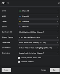
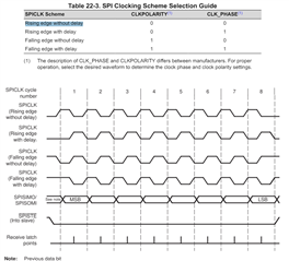
I am trying to understand the SPI Configuration settings. After reading the Technical Reference Manual for SPI, I still have no idea what I'm doing.
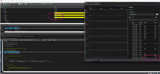
Im using a LaunchpadXL-TMS320F2800157 directly connected to my Salae LA.
- Specifically, the interrupts for SPI and how exactly the transmit interrupt is triggered in this example "spi_ex2_lookback_fifo_interrupts" since there is nothing in the program to fill the transmit FIFO thus how is it possible for the ISR to trigger?
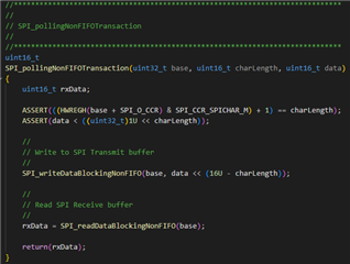
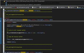
- Additionally, has anyone fixed the SPI driver for "SPI_pollingNonFIFOTransaction". I still have erratic clock behavior that others see here when using that: https://e2e.ti.com/support/microcontrollers/c2000-microcontrollers-group/c2000/f/c2000-microcontrollers-forum/1248486/tms320f280025c-issues-with-manual-control-of-cs-pin-in-spi-when-using-driverlib-functions/4726334?tisearch=e2e-sitesearch&keymatch=SPI_pollingNonFIFOTransaction#4726334
-
It would be super helpful if someone could share an interrupt-based SPI project that works with sending multiple bytes and using GPIO as Chip Select Pin.
Best - Gray
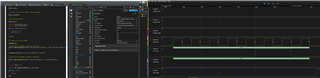
Code snippet from default project: (How does the Transmit ISR trigger to send data when there is nothing to fill the FIFO and trigger an interrupt)
Thank you so much for your help in advance. Sorry Im a novice to programming, SPI, and Embedded software.