


Part Number: TMS320F28386D
Hi All
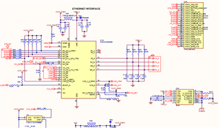
I am configuring Ethernet on my custom board (TMS320F28386D) using example code cm_common_config_c28x.c and ethernet_ex1_basic_tx_rx_loopback.c and its not working .
The problem is that I don't know whether my configuration is right or wrong because i am new in
Ethernet.   so please check my code and schematic that where i am stuck

below is my schematic and code


void main(void)
{

 //
 // Initialize device clock and peripherals
 //
 Device_init();

 //
 // Boot CM core
 //
#ifdef _FLASH
 Device_bootCM(BOOTMODE_BOOT_TO_FLASH_SECTOR0);
#else
 Device_bootCM(BOOTMODE_BOOT_TO_S0RAM);
#endif

 //
 // Disable pin locks and enable internal pull-ups.
 //
 Device_initGPIO();

#ifdef ETHERNET
 //
 // Set up EnetCLK to use SYSPLL as the clock source and set the
 // clock divider to 2.
 //
 // This way we ensure that the PTP clock is 100 MHz. Note that this value
 // is not automatically/dynamically known to the CM core and hence it needs
 // to be made available to the CM side code beforehand.
 SysCtl_setEnetClk(SYSCTL_ENETCLKOUT_DIV_2, SYSCTL_SOURCE_SYSPLL);

 //
 // Configure the GPIOs for ETHERNET.
 //

 //
 // / 1 PIN
 GPIO_setPinConfig(GPIO_35_ENET_MII_COL);


 // 2ND PIN
 GPIO_setPinConfig(GPIO_40_ENET_MII_CRS);


 // 3RD PIN
 // GPIO_setPinConfig( GPIO_41_ENET_REVMII_MDIO_RST);
 GPIO_setDirectionMode(41, GPIO_DIR_MODE_OUT);
 GPIO_setPadConfig(41, GPIO_PIN_TYPE_PULLUP);
 GPIO_writePin(41,1);

 // 4TH PIN
 GPIO_setPinConfig(GPIO_50_ENET_MII_RX_DV );


 // 5TH PIN
 GPIO_setPinConfig(GPIO_51_ENET_MII_RX_ERR );


 // 6TH PIN
 GPIO_setPinConfig(GPIO_52_ENET_MII_RX_DATA0 );


 // 7TH PIN
 GPIO_setPinConfig(GPIO_53_ENET_MII_RX_DATA1);


 // 8TH PIN
 GPIO_setPinConfig(GPIO_54_ENET_MII_RX_DATA2);


 // 9TH PIN
 GPIO_setPinConfig(GPIO_55_ENET_MII_RX_DATA3);


 // 10TH PIN
 GPIO_setPinConfig(GPIO_56_ENET_MII_TX_EN);


 // 11TH PIN
 GPIO_setPinConfig( GPIO_59_ENET_MII_TX_DATA0 );


 // 12TH PIN
 GPIO_setPinConfig(GPIO_60_ENET_MII_TX_DATA1 );


 // 13TH PIN
 GPIO_setPinConfig(GPIO_61_ENET_MII_TX_DATA2 );


 // 14TH PIN
 GPIO_setPinConfig(GPIO_62_ENET_MII_TX_DATA3 );


 // 15TH PIN
 GPIO_setPinConfig(GPIO_44_ESC_TX1_CLK );


 // 16TH PIN
 GPIO_setPinConfig(GPIO_42_ENET_MDIO_CLK );


 // 17TH PIN
 GPIO_setPinConfig(GPIO_43_ENET_MDIO_DATA );


 // 18TH PIN
 GPIO_setPinConfig(GPIO_67_ENET_MII_RX_CLK );


 // 19TH PIN
 // GPIO_setPinConfig( GPIO_68_ENET_MII_INTR);
 GPIO_setDirectionMode(68, GPIO_DIR_MODE_OUT);
 GPIO_setPadConfig(68, GPIO_PIN_TYPE_PULLUP);
 GPIO_writePin(68,1);
#endif

#ifdef MCAN
 //
 // Setting the MCAN Clock.
 //
 SysCtl_setMCANClk(SYSCTL_MCANCLK_DIV_4);

 //
 // Configuring the GPIOs for MCAN.
 //
 GPIO_setPinConfig(DEVICE_GPIO_CFG_MCANRXA);
 GPIO_setPinConfig(DEVICE_GPIO_CFG_MCANTXA);
#endif

#ifdef CANA
 //
 // Configuring the GPIOs for CAN A.
 //
 GPIO_setPinConfig(DEVICE_GPIO_CFG_CANRXA);
 GPIO_setPinConfig(DEVICE_GPIO_CFG_CANTXA);

 //
 // Allocate Shared Peripheral CAN A to the CM Side.
 //
 SysCtl_allocateSharedPeripheral(SYSCTL_PALLOCATE_CAN_A,0x1U);
#endif

#ifdef CANB
 //
 // Configuring the GPIOs for CAN B.
 //
 GPIO_setPinConfig(DEVICE_GPIO_CFG_CANRXB);
 GPIO_setPinConfig(DEVICE_GPIO_CFG_CANTXB);

 //
 // Allocate Shared Peripheral CAN B to the CM Side.
 //
 SysCtl_allocateSharedPeripheral(SYSCTL_PALLOCATE_CAN_B,0x1U);
#endif

#ifdef UART
 //
 // Configure GPIO85 as the UART Rx pin.
 //
 GPIO_setPinConfig(GPIO_85_UARTA_RX);
 GPIO_setDirectionMode(85, GPIO_DIR_MODE_IN);
 GPIO_setPadConfig(85, GPIO_PIN_TYPE_STD);
 GPIO_setQualificationMode(85, GPIO_QUAL_ASYNC);

 //
 // Configure GPIO84 as the UART Tx pin.
 //
 GPIO_setPinConfig(GPIO_84_UARTA_TX);
 GPIO_setDirectionMode(84, GPIO_DIR_MODE_OUT);
 GPIO_setPadConfig(84, GPIO_PIN_TYPE_STD);
 GPIO_setQualificationMode(84, GPIO_QUAL_ASYNC);
#endif

#ifdef USB
#ifdef USE_20MHZ_XTAL
 //
 // Set up the auxiliary PLL so a 60 MHz output clock is provided to the USB module.
 // This fixed frequency is required for all USB operations.
 //
 SysCtl_setAuxClock(SYSCTL_AUXPLL_OSCSRC_XTAL |
 SYSCTL_AUXPLL_IMULT(48) |
 SYSCTL_REFDIV(2U) | SYSCTL_ODIV(4U) |
 SYSCTL_AUXPLL_DIV_2 |
 SYSCTL_AUXPLL_ENABLE |
 SYSCTL_DCC_BASE_0);
#else
 //
 // Set up the auxiliary PLL so a 60 MHz output clock is provided to the USB module.
 // This fixed frequency is required for all USB operations.
 //
 SysCtl_setAuxClock(SYSCTL_AUXPLL_OSCSRC_XTAL |
 SYSCTL_AUXPLL_IMULT(48) |
 SYSCTL_REFDIV(2U) | SYSCTL_ODIV(5U) |
 SYSCTL_AUXPLL_DIV_2 |
 SYSCTL_AUXPLL_ENABLE |
 SYSCTL_DCC_BASE_0);
#endif

 //
 // Allocate Shared Peripheral USB to the CM Side.
 //
 SysCtl_allocateSharedPeripheral(SYSCTL_PALLOCATE_USBA, 1);

 GPIO_setPinConfig(GPIO_0_GPIO0);
 GPIO_setPadConfig(0, GPIO_PIN_TYPE_STD);
 GPIO_setDirectionMode(0, GPIO_DIR_MODE_OUT);
 GPIO_setMasterCore(0, GPIO_CORE_CM);

 //
 // Set the master core of GPIOs to CM.
 //
 GPIO_setMasterCore(42, GPIO_CORE_CM);
 GPIO_setMasterCore(43, GPIO_CORE_CM);
 GPIO_setMasterCore(46, GPIO_CORE_CM);
 GPIO_setMasterCore(47, GPIO_CORE_CM);
 GPIO_setMasterCore(120, GPIO_CORE_CM);
 GPIO_setMasterCore(121, GPIO_CORE_CM);

 //
 // Set the USB DM and DP GPIOs.
 //
 GPIO_setAnalogMode(42, GPIO_ANALOG_ENABLED);
 GPIO_setAnalogMode(43, GPIO_ANALOG_ENABLED);

 //
 // Set the direction for VBUS and ID.
 //
 GPIO_setDirectionMode(46, GPIO_DIR_MODE_IN);
 GPIO_setDirectionMode(47, GPIO_DIR_MODE_IN);

 //
 // Configure the Power Fault.
 //
 GPIO_setMasterCore(120, GPIO_CORE_CM);
 GPIO_setDirectionMode(120, GPIO_DIR_MODE_IN);

 //
 // Configure the External Power Signal Enable.
 //
 GPIO_setMasterCore(121, GPIO_CORE_CM);
 GPIO_setDirectionMode(121, GPIO_DIR_MODE_OUT);
 GPIO_writePin(121, 1);

 //
 // Set the CM Clock to run at 120MHz.
 // The CM Clock is a fractional multiple of the AUXPLL Clock (120 Mhz) from
 // which the USB Clock (60 MHz) is derived.
 //
 SysCtl_setCMClk(SYSCTL_CMCLKOUT_DIV_1, SYSCTL_SOURCE_AUXPLL);
#endif
}

void main(void)
{
 Ethernet_InitInterfaceConfig initInterfaceConfig;
 Ethernet_InitConfig *pInitCfg;
 Ethernet_Pkt_Desc pktDesc;
 uint32_t i;
 Ethernet_Statistics stats;
 Ethernet_Handle emac_handle;

 //
 // Initialize device clock and peripherals
 //
 CM_init();

 //
 //Form the unicast Packet in Memory
 //
 for(i=0;i<PACKET_LENGTH/4;i++)
 {
 //
 //First 6 bytes of the packet are the MAC Destination Address
 //Bytes, the Destination and CRC shall be inserted by the hardware
 //
 if(i == 0)
 *((uint32_t *)pData + i) = 0x01020304;
 else if(i == 1)
 *((uint32_t *)pData + i) = 0xFFFF0506;
 else
 HWREG((uint32_t *)pData +i) = 0xFFFFFFFF;
 }

 //
 //Select the MII interface of the module
 //
 initInterfaceConfig.ssbase = EMAC_SS_BASE;
 initInterfaceConfig.enet_base = EMAC_BASE;
 initInterfaceConfig.phyMode = ETHERNET_SS_PHY_INTF_SEL_MII;
 //
 //Assign SoC specific functions for Enabling,Disabling interrupts
 //and for enabling the Peripheral at system level
 //
 initInterfaceConfig.ptrPlatformInterruptDisable = &Platform_disableInterrupt;
 initInterfaceConfig.ptrPlatformInterruptEnable = &Platform_enableInterrupt;
 initInterfaceConfig.ptrPlatformPeripheralEnable = &Platform_enablePeripheral;
 initInterfaceConfig.ptrPlatformPeripheralReset = &Platform_resetPeripheral;
 //
 //Assign the peripheral number at the SoC
 //
 initInterfaceConfig.peripheralNum = SYSCTL_PERIPH_CLK_ENET;
 //
 //Assign the default SoC specific interrupt numbers of Ethernet interrupts
 //
 initInterfaceConfig.interruptNum[0] = INT_EMAC;
 initInterfaceConfig.interruptNum[1] = INT_EMAC_TX0;
 initInterfaceConfig.interruptNum[2] = INT_EMAC_TX1;
 initInterfaceConfig.interruptNum[3] = INT_EMAC_RX0;
 initInterfaceConfig.interruptNum[4] = INT_EMAC_RX1;

 pInitCfg = Ethernet_initInterface(initInterfaceConfig);

 //
 // Get an initial configuration of known good parameters
 //
 Ethernet_getInitConfig(pInitCfg);

 //
 //Configure the Loopback mode
 //
 pInitCfg->loopbackMode = ETHERNET_MAC_CONFIGURATION_LM_LOOPBACK_ENABLED;

 //
 //Assign the callbacks for Getting packet buffer when needed
 //Releasing the TxPacketBuffer on Transmit interrupt callbacks
 //Receive packet callback on Receive packet completion interrupt
 //
 pInitCfg->pfcbGetPacket = &Ethernet_getPacketBuffer;
 pInitCfg->pfcbFreePacket = &Ethernet_releaseTxPacketBuffer;
 pInitCfg->pfcbRxPacket = &Ethernet_receivePacketCallback;
 //
 //Assign the Buffer to be used by the Low level driver for receiving
 //Packets. This should be accessible by the Ethernet DMA
 //
 pInitCfg->rxBuffer = Ethernet_rxBuffer;

 //
 //The Application handle is not used by this application
 //Hence using a dummy value of 1
 //
 Ethernet_getHandle((Ethernet_Handle)1,pInitCfg , &emac_handle);
 //
 //Do global Interrupt Enable
 //
 (void)Interrupt_enableInProcessor();
 //
 //Assign default ISRs
 //
 Interrupt_registerHandler(INT_EMAC_TX0, Ethernet_transmitISR);
 Interrupt_registerHandler(INT_EMAC_RX0, Ethernet_receiveISR);
 //
 //Enable the default interrupt handlers
 //
 Interrupt_enable(INT_EMAC_TX0);
 Interrupt_enable(INT_EMAC_RX0);

 //
 //Prepare a Packet Descriptor structure to send a packet
 //This contains a single buffer packet
 //The Source address shall be inserted by the MAC
 //Packet CRC is auto computed by the module and appended in the packet
 //
 pktDesc.bufferLength = PACKET_LENGTH;
 pktDesc.dataOffset = 0;
 pktDesc.dataBuffer = pData;
 pktDesc.nextPacketDesc = 0;
 pktDesc.flags = ETHERNET_PKT_FLAG_SOP |ETHERNET_PKT_FLAG_EOP|ETHERNET_PKT_FLAG_SA_INS;
 pktDesc.pktChannel = ETHERNET_DMA_CHANNEL_NUM_0;
 pktDesc.pktLength = PACKET_LENGTH;
 pktDesc.validLength = PACKET_LENGTH;
 pktDesc.numPktFrags = 1;

 //
 //Send the packet prepared
 //
 Ethernet_sendPacket(emac_handle,&pktDesc);

 //
 //Delay for the MAC to send the packet on the wire and receive it
 //
 SysCtl_delay(3000);

 //
 //Read the statistics of the Module
 //
 Ethernet_getStatistics(emac_handle, &stats);

 //
 //Check if a packet has been received
 //
 if(!stats.rxUnicastPacketsGood)
 __asm(" bkpt #0");

}


Thanks

