This thread has been locked.

If you have a related question, please click the "Ask a related question" button in the top right corner. The newly created question will be automatically linked to this question.

TMS320F280039: Shoot-through despite of dead-band module

Part Number: TMS320F280039
Other Parts Discussed in Thread: C2000WARE, PMP

Hello TI support team, 

I am working on implementing symmetrical peak-current control as it is described in https://www.ti.com/tool/PMP23069.

Strangely, the T1 events are causing shoot-throughs on the active-to-passive leg, even though the dead-band module is used.

Here is the relevant DB configuration code:

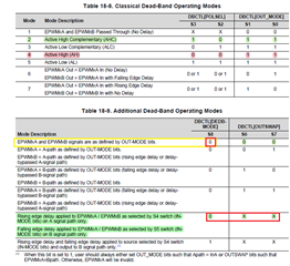
EPWM_setRisingEdgeDeadBandDelayInput(EPWM5_BASE, EPWM_DB_INPUT_EPWMA);
EPWM_setFallingEdgeDeadBandDelayInput(EPWM5_BASE, EPWM_DB_INPUT_EPWMA);
EPWM_setDeadBandDelayMode(EPWM5_BASE, EPWM_DB_RED, true);
EPWM_setDeadBandDelayMode(EPWM5_BASE, EPWM_DB_FED, true);

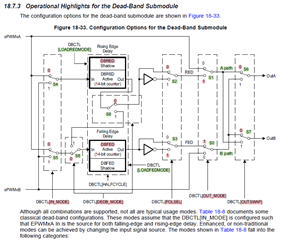
Since FED and RED are supplied by the same signal (EPWM_DB_INPUT_EPWMA), I do not understand how there could possibly be any shoot-throughs.

I would expect dead-time to be always properly inserted independently of what the shape and form of INPUT_EPWMA is.

Note that if I disable the T1 events by setting the CMPSS DAC to a high enough value, the PWM5A/B pins behave as expected, with the correct dead-time in place.

Any insights would be much appreciated.

Thank you,

Beat

  • Beat,

    I'm assuming you are configuring PWMB to be the inverted version of PWMA in the dead band configuration since RED and FED input is always EPWMA.

    What is your AQ configuration for the T1 events? 

  • Hello Gus - thank you for your response.

    Yes, PWMB is configured as the inverted version of PWMA with dead-time inserted, and hence my confusion about seeing (substantial!) overlap, resulting in half-bridge shoot-through when the T1 event is active. 

    Here is the AQ configuration:

    EPWM_setActionQualifierT1TriggerSource(EPWM5_BASE,
                                         EPWM_AQ_TRIGGER_EVENT_TRIG_DC_EVTFILT);
    
    EPWM_setActionQualifierAction(EPWM5_BASE, EPWM_AQ_OUTPUT_A,
                                EPWM_AQ_OUTPUT_HIGH,
                                EPWM_AQ_OUTPUT_ON_T1_COUNT_UP);
    EPWM_setActionQualifierAction(EPWM5_BASE, EPWM_AQ_OUTPUT_A,
                                EPWM_AQ_OUTPUT_LOW,
                                EPWM_AQ_OUTPUT_ON_T1_COUNT_DOWN);
    
    EPWM_setActionQualifierAction(EPWM5_BASE, EPWM_AQ_OUTPUT_A,
                                EPWM_AQ_OUTPUT_NO_CHANGE,
                                EPWM_AQ_OUTPUT_ON_TIMEBASE_UP_CMPA);
    EPWM_setActionQualifierAction(EPWM5_BASE, EPWM_AQ_OUTPUT_A,
                                EPWM_AQ_OUTPUT_NO_CHANGE,
                                EPWM_AQ_OUTPUT_ON_TIMEBASE_DOWN_CMPA);
    
    EPWM_setActionQualifierAction(EPWM5_BASE, EPWM_AQ_OUTPUT_A,
                                  EPWM_AQ_OUTPUT_LOW,
                                  EPWM_AQ_OUTPUT_ON_TIMEBASE_ZERO);
    EPWM_setActionQualifierAction(EPWM5_BASE, EPWM_AQ_OUTPUT_A,
                                  EPWM_AQ_OUTPUT_HIGH,
                                  EPWM_AQ_OUTPUT_ON_TIMEBASE_PERIOD);

    But then again, I don't see how this could possibly be relevant, as these settings apply upstream from the dead-band module, and only affect the signal EPWM_DB_INPUT_EPWMA going into the dead-band module. I would expect to see a complementary version of EPWM_DB_INPUT_EPWMA at the EPM5A/B pins, with dead-time inserted, no matter what the AQ configuration is.

    Kind regards,

    Beat

  • Beat,

    OK, yes, I see your point. In complementary mode the T1 even configuration shouldn't matter to this problem you are facing.

    Can you share a scope plot of the PWM signals in question?

    You may also want to check the deadband example in c2000ware.

    C:\ti\c2000\C2000Ware_5_01_00_00\driverlib\f28003x\examples\epwm

  • Hello Gus,

    OK. Here are some measurements to illustrate the issue.

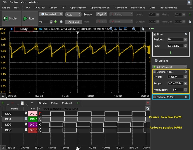
    The scope image below shows, in yellow, the bridge current measurement as seen by the ADC B11 pin, which is connected to the CMPSS HP pin (CMP4_HP5)

    The digital traces below correspond to the complementary PWM signals for the passive-to-active and active-to-passive legs. As you can see, they are slightly phase shifted. Both are configured with AQ events on Z and P, additionally the active-to-passive legs has T1 events configured (as shown in code snippet above). All compare events are disabled.

    This measurement is taken with the CMPSS DAC value (DACHVALA) set above the comparator input, and therefore the T1 event is never fired and the active-to-passive leg is nice and complementary with deadtime inserted as per the discussion above.

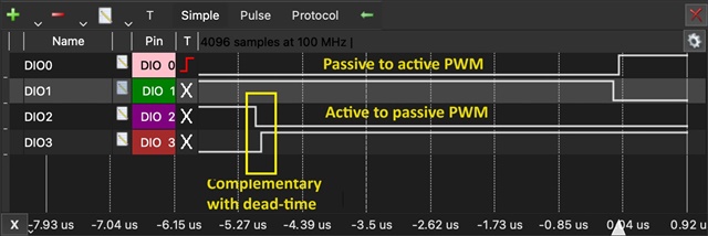
    Here is a zoomed-in measurement of the PWM signals showing correct deadtime and zero shoot-through.

    This operation without T1 events works without issue with a real powerstage.

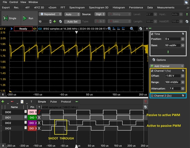
    But if I now lower the CMPSS DAC value (by means CMPSS_setMaxRampValue) such that T1 events occur, the active-to-passive PWM becomes no longer complementary, resulting in short-throughs on the active-passive leg.

    See following traces.


    To be very clear, the only change compared to the other measurements is that I lowered the CMPSS DAC value (by means CMPSS_setMaxRampValue) such that T1 events occur.

    I hope that these measurements are helpful for your analysis.

    Happy to run further tests and measurements based on your recommendations.

    Kind regards,

    Beat

  • Beat,

    The Trip Zone module in the PWM also has the ability to override the AQ and DB modules by controlling the EPWM_A and EPWM_B outputs directly. Are you using this module at all in your code?

  • Hi Beat,

    EPWM_setFallingEdgeDeadBandDelayInput(EPWM5_BASE, EPWM_DB_INPUT_EPWMA);

    Seemingly for true complementary PWM drive signal pair dead band generator require separate inputs, shadow load A/B comparators. The invert A to make B scenario on some DB generators can produce periods of uncertainty where A remains high so many clocks. Perhaps separate DB inputs assign _EPWB too. Depending on up/down count (typical for complementary signal pair) mode and edge alignment method discussed in Technical Resource manual.

    Question, why setting different time source for low/high signal direction via CMPA?

    EPWM_setActionQualifierAction(EPWM5_BASE, EPWM_AQ_OUTPUT_A,
    EPWM_AQ_OUTPUT_LOW,
    EPWM_AQ_OUTPUT_ON_TIMEBASE_ZERO);
    EPWM_setActionQualifierAction(EPWM5_BASE, EPWM_AQ_OUTPUT_A,
    EPWM_AQ_OUTPUT_HIGH,
    EPWM_AQ_OUTPUT_ON_TIMEBASE_PERIOD);

  • Hi Gus, I don't want to use the TZ as a workaround before I fully understand what is going on.

  • Hello Genatco,

    This is an interesting suggestion. I will try to use the second action qualifier and independent paths through the deadband module and see if that makes a difference.

    Could you please point me to the relevant section in the TRM that explains this DB issue with "periods of uncertainty"?

    As for your question, I am not using any compare actions. The AQ is configured to produce a signal with 50% duty cycle in up-down count mode using solely zero and period actions. The "active-passive" leg of the phase-shifted full-bridge is configured for inverted actions compared to the "passive-active" leg, and utilizes T1 actions to achieve a phase shift for peak-current control (see PMP 23069).

  • I wasn't suggesting you use TZ, just wanted to point out that it's something to look at. By default TZ is configured to place the pins in high-z, which is something to keep in mind. You provided logic analyzer captures of the PWM pins so maybe something that may be missed?

  • Could you please point me to the relevant section in the TRM that explains this DB issue with "periods of uncertainty"?

    Perhaps was a general issue with revision 2 PWM module DB generators, both outputs could randomly be high during the same clock period. The other question why not use zero switching technique was very popular for some time to reduce noise, the TRM section PWM uses shows phase shifted zero crossing configuration. Can you show your phase shift setup code? Perhaps that can be possible issue with DB generation and two different TB action qualifiers when duty cycle updates are set for shadowed global or immediate? A split DB mode was not exactly spelled out in C2000 driverlib, added a struct member, So the symbol name was more recognized as being split (complementary) dead band control via (A/B) inputs.

    This DB switches diagram x49c for complementary signals where CMPA/B are loaded with the duty cycle value.

  • Hello Gus, this is it!

    In my code, the T1 event is generated by DCBEVT2, and indeed, I was unaware that DCBEVT2 also comes with the default action to place the PWM B pin into high impedance!

    Once I configured TZCTL.DCBEVT2 to 3, the problem disappeared.

    Thank you (also @Genatco) for helping me get this resolved.

    Beat

  • Bizarre the trip zone action qualifier (default POR register values) has anything to do with dead band generation on the B output as the dead band diagram depicted in the TRM has no CCMPSS connections.

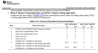
    Even if ePWM_B output entered into high impedance it should be ignored by the dead band generators ePWMxB input - right? The DBCTL (HalfCycle) input seemingly would affect both dead band outputs in the same way.

    Perhaps the DB operating mode is configured for complementary outputs after all and the ePWMxB input is indeed being asserted.